Tag Archive: Design


I passed the ARCH exam!

It’s been a while since I’ve posted something here. Multiple reasons of course, but lately I just had to focus on learning so much I didn’t take the time for it anymore. Why? Well since I got my CCNP almost three years ago, it had to be recertified. Together with my CCDA that presented the opportunity to gain a CCDP certification and renewing my CCNP at once by just taking one more exam: ARCH.

So it’s been done. Was it hard? I honestly don’t know. So much has changed this last year for me: how I look at my profession, how I look at learning, at certifications,… I can’t compare it anymore to past experiences. So many things I learned outside of the certification path that are so important to have insights as an engineer… Examples like TCP Windowing, ASIC behavior, VRF deployment, application behavior in LAN and WAN (Citrix, SCP, FTP, NTP, vMotion, SCCM), load balancing and SSL offloading, …

All I know that this was a lot of (useful) theory and I had to devise a plan to learn it all, which eventually succeeded. So besides the certification I improved my ability to learn with it. And that in turn gives me strength for the next one: CCIEv5.

Yes, there I said it. For over a year I kept doubting it a bit, saying I wanted it but not putting a date on it. That’s over now. In a month I’ll start preparing the written with hopefully the exam in the first quarter of 2015.

I am ready.

Advantages of MPLS: an example.

While MPLS is already explained on this blog, I often still get questions regarding the advantages over normal routing. A clear example I’ve also already discussed, but besides VRF awareness and routing of overlapping IP ranges, there’s also the advantage of reduced resources required (and thus scalability).

WANEdgeDesign

Given the above design: two routers connecting towards ISPs using eBGP sessions. These in turn connect to two enterprise routers, and those two enterprise routers connect towards two backend routers closer to (or in) the network core. All routers run a dynamic routing protocol (e.g. OSPF) and see each other and their loopbacks. However, the two middle routers in the design don’t have the resources to run a full BGP table so the WAN edge routers have iBGP sessions with the backend routers near the network core.

If you configure this as described and don’t add any additional configuration, this design will not work. The iBGP sessions will come up and exchange routes, but those routes will list the WAN edge router as the next hop. Since this next hop is not on a directly connected subnet to the backend routers, the received routes will not be installed in the routing table. The enterprise routers would not have any idea what to do with the packets anyway.

Update January 17th, 2014: the real reason a route will not be installed in the routing table is the iBGP synchronisation feature, which requires the IGP to have learned the BGP routes through redistribution before using the route. Still, synchronisation can be turned off and the two enterprise routers would drop the packets they receive.

There are a few workarounds to make this work:

  • Just propagating a default route of course, but since the WAN edge routers are not directly connected to each other and do not have an iBGP session, this makes the eBGP sessions useless. Some flows will go through one router, some through the other. This is not related to the best AS path, but to the internal (OSPF) routing.
  • Tunneling over the middle enterprise routers, e.g. GRE tunnels from the WAN edge routers towards the backend routers. Will work but requires multiple tunnels with little scalability and more complex troubleshooting.
  • Replacing the middle enterprise routers by switches so it becomes layer 2 and the WAN edge and backend routers have a directly connected subnet. Again this will work but requires design changes and introduces an extra level of troubleshooting (spanning tree).

So what if MPLS is added to the mix? By adding MPLS to these 6 routers (‘mpls ip’ on the interfaces and you’re set), LDP sessions will form… After which the backend routers will install all BGP routes in their routing tables!

The reason? LDP will advertise a label for each prefix in the internal network (check with ‘show mpls ldp bindings’) and a label will be learned for the interfaces (loopback) of the WAN edge routers… After which the backend routers know they just have to send the packets towards the enterprise routers with the corresponding MPLS label.

And the enterprise routers? They have MPLS enabled on all interfaces and no longer use the routing table or FIB (Forwarding Information Base) for forwarding, but the LFIB (Label Forwarding Information Base). Since all packets received from the backend routers have a label which corresponds to the loopback of one of the WAN edge routers, they will forward the packet based on the label.

Result: the middle enterprise routers do not need to learn any external routes. This design is scalable and flexible, just adding a new router and configuring OSPF and MPLS will make it work. Since a full BGP table these days is well over 450,000 routes, the enterprise routers do not need to check a huge routing table for each packet which decreases resource usage (memory, CPU) and decreases latency and jitter.

I have to admit, this article will sound a bit like an advertisement. But given that Cisco has gotten enough attention on this blog already, it can only bring variation into the mix.

A short explanation of a series of different products offered by F5 Networks. Why? If you’re a returning reader to this blog and work in the network industry, chances are you’ll either have encountered one of these appliances already, or could use them (or another vendor’s equivalent of course).

F5-LTM

LTM
The Local Traffic Manager’s main function is load balancing. This means it can divide incoming connections over multiple servers.
Why you would want this:
A typical web server will scale up to a few hundred or thousand connections, depending on the hardware and services it is running and presenting. But there may be more connections needed than one server can handle. Load balancing allows for scalability.
Some extra goodies that come with it:

  • Load balancing method: of course you can choose how to divide the connections. Simply round-robin, weighted in favor of a better server that can handle more, always to the server with the least connections,…
  • SSL Offloading: the LTM can provide the encryption for HTTPS websites and forward the connections in plain HTTP to the web servers, so they don’t have to consume CPU time for encryption.
  • OneConnect: instead of simply forwarding each connection to the servers in the load balancing pool, the LTM can set up a TCP connection with each server and reuse it for every incoming connection, e.g. a new HTTP GET for each external connection over the same inbound connection. Just like SSL Offloading, it consumes fewer resources on the servers. (Not every website handles this well.)
  • Port translation: not really NAT but you can configure the LTM for listening on port 80 HTTP or 443 HTTPS while the servers have their webpage running on different ports.
  • Health checks: if one of the servers in the pool fails, the LTM can detect this and stop sending connections to the server. The service or website will stay up, it will just be able to accept fewer resources. You can even upgrade servers one by one without downtime for the website (but make sure to plan this properly).
  • IPv6 to IPv4 translation: your web servers and entire network does not have to be IPv6 capable. Just the network up to the LTM has to be.

F5-ASM

ASM
The Application Security Manager can be placed in front of servers (one server per external IP address) and functions as an IPS.
Why you would want this:
If you have a server reachable from the internet, it is vulnerable to attack. Simple as that. Even internal services can be attacked.
Some extra goodies that come with it:

  • SSL Offloading: the ASM can provide the encryption for HTTPS websites just like the LTM. The benefit here is that you can check for attack vectors inside the encrypted session.
  • Automated requests recognition: scanning tools can be recognized and prevented access to the website or service.
  • Geolocation blocks: it’s possible to block out entire countries with automatic lists of IP ranges. This way you can offer the service only where you want it, or stop certain untrusted regions from connecting.

GTM
The Global Traffic Manager is a DNS forwarding service that can handle many requests at the same time with some custom features.
Why you would want this:
This one isn’t useful if the service you’re offering isn’t spread out over multiple data centers in geographically different regions. If it is, it will help redirect traffic to the nearest data center and provide some DDoS resistance too.
Some extra goodies that come with it:

  • DNSSec: secured DNS support which prevents spoofing.
  • Location-based DNS: by matching the DNS request with a list of geographical IP allocations, the DNS reply will contain an A record (or AAAA record) that points to the nearest data center.
  • Caching: the GTM also caches DNS requests to respond faster.
  • DDoS proof: automated DNS floods are detected and prevented.

F5-APM

APM
The Access Policy Manager is a device that provides SSLVPN services.
Why you would want this:
The APM will connect remote devices with encryption to the corporate network with a lot of security options.
Some extra goodies that come with it:

  • SSLVPN: no technical knowledge required for the remote user and works over SSL (TCP 443) so there’s a low chance of firewalls blocking it.
  • SSO: Single Sign On support. Log on to the VPN and credentials for other services (e.g. Remote Desktop) are automatically supplied.
  • AAA: lots of different authentication options, local, Radius, third-party,…
  • Application publishing: instead of opening a tunnel, the APM can publish applications after the login page (e.g. Remote Desktop, Citrix) that open directly.

So what benefit would you have from knowing this? More than you think: many times when a network or service is designed, no attention is given to these components. Yet they can help scale out a service without resorting to complex solutions.

CCDA certified!

Yes, another certificate! I took the exam last Monday and I passed. Although I have to admit, I didn’t find this exam easy. At all. But it’s have to compare with past exams because I haven’t taken one in the last year and a half.

That’s also the reason why: my previous certificates will expire in a little over a year. I still want that CCIE but I’m becoming uncertain if I will get it by then, and my company expects a certificate every now and then.

Up next: most likely CCDP. It will require just one exam, ARCH, since I passed ROUTE and SWITCH less than three years ago, and it will recertify my CCNP as well.

As for the CCDA content: interesting and I really learned things, but it’s not one I’d recommend for any engineer. The Routing & Switching track is much more of a challenge.

Best luck to all studying out there!

Initially, I told myself I wasn’t going to spend an entire blog post to the new 3850 switch. Presented on Cisco Live London, it was just a new series of Catalyst switches with all existing functionality plus some new things like the integrated WLC. Not really interested in anything else, I got bored and Googled around to see if my WS-C3560-8PC fanless desktop switch had a gigabit equivalent. Turns out it does, with quite a few models. All fanless, PoE capabilities and some layer 3 models. But then I noticed something: some of these models had both PoE powering and PoE powered ports. So how does that work? Well, these switches have two PoE powered ports. Some power is used for the switch itself and the remainder is used in the PoE budget towards the switches. The switches can give standard 802.3af PoE at 15.4W per port, but can receive 802.3af (15.4W), 802.3at PoE+ (25,5W) or UPoE. UPoE isn’t an official standard yet, but Cisco is pushing for it and their new 3850 series supports it. It allows up to 60 Watts per port.

And then it hit me. 3850’s, compact switches, and other PoE devices like Access Points and IP Phones allow for a lot of interesting designs.

PoE-Office

For example, using the 3850 in a stack as a core switch in an office, it’s possible to give power to fanless (silent) compact switches near the desks. The C2960CPD-8PT (what a name!) has two powered PoE uplinks so a 2 Gbps port-channel towards the 3850 stack is possible. That gives redundancy when spread over two switches, and the stack can also use StackPower. It’s max power budget is 30W, which is enough for two PoE devices, or more when using 802.3af classes or CDP PoE negotiation, e.g. many IP Phones only use 7 Watt, allowing for four on one switch. Result: it’s possible to power an entire office network directly from the core: less wall sockets needed, less cable runs. And finally, the integrated WLC on the 3850 allows all AP tunnels to terminate in the office itself, instead of going back towards a remote controller in a HQ/Data Center. This allows faster and easier access to local resources (printers, on-site servers).

The combination 3850/Compact switches allows for long cable runs without any need for a power supply anywhere in between. In the most extreme case you can bridge 500 meters with it: 3850, 100m copper  UPoE, 2960CPD, 100m PoE, 2960C, and a 100m cable run towards a mirrored setup.

So yes, when thinking about it, these new switches with new technology do allow more flexibility when deploying a network!

I regularly see questions about IPv6 subnetting (despite the fact that the answers are out there with a simple Google search). ‘How do you subnet in IPv6?’ Well, there are some general guidelines that can help you a long way.

An IPv6 address is 128 bits, so prefix size can vary between /0 and /128. I’m going to list prefix sizes and their meanings below here, but remember, these are guidelines, and in no way mandatory. If you want to make a /103 subnet, you can do that.

  • A /64 is considered a basic subnet in IPv6. Reason for this is Stateless Address Autoconfiguration, or SLAAC (covered in RFC 4291). This is a method in which an IPv6 host forms his own address using the MAC address and the /64 prefix advertised by a router in the broadcast domain. It only works on /64, hence why you will usually see a lot of /64 subnets in an IPv6 network. Visually they are easy too: the first four sedets (there’s no definitive naming convention how to call a group of 16 bits in an IPv6 address) are the network part, the last four sedets the host part.
  • A /127 is a point-to-point link, as IPv6 has no concept of network and broadcast addresses. While many use a /64 on point-to-point links as well so the routing table looks simple, a /127 can more secure to work with.
  • A standard network with subnets is a /56, which gives 256 subnets (eight bits), each a /64. This is usually enough for a small to even medium network and should be considered a minimum assigned address space by an ISP for one connection (RFC 6177 refers to this best-practice).
  • A more common assignment by a provider, and a former best-practice, is a /48. It makes the visual part of addressing easy again: the first three sedets are the globally routed prefix, the fourth sedet is used for internal subnetting, and the remaining four sedets are again the host part for the /64 subnets. A /48 prefix is the smallest prefix allowed by most carriers in a global BGP routing table. It can also be seen in large companies that efficiently use route summarization.
  • Anything bigger, /44, /40, /32, are globally assigned IPv6 address spaces to companies with their own Autonomous System number, just like IPv4 global address space. You’re not likely to see this outside a BGP routing table.
  • A /16 is only used so far for 2002::/16 (6to4 addresses), just like a FE80::/10 (link-local),  FF00::/8 (multicast) and FC00::/7 (unique-local) addresses. None of these should ever appear in a routing table.
  • Finally a /0 refers to ::/0, which is a default route, just like IPv4’s 0.0.0.0/0 route.

As you may have noticed by now, subnetting in IPv6 is done for efficient route summarization, not conserving address space. Why would you? This is why a /103 subnet would not be necessary, although together with DHCPv6, you can perfectly make such a subnet work.

IPv4 anycast design.

Today, not a new protocol or device, but something else: an anycast design. In IPv6, an anycast address is an address that is in use by multiple devices. A packet destined for this address is sent to one of the devices only, either at random, load balanced, or by shortest distance (geographical location or metric). This article will show a design that does that in IPv4. The anycast service used will be DNS, but it can be anything, going from DNS, DHCP, NTP to protocols that use sessions like HTTP, although it does not provide any stateful failover in case a server fails.

AnycastDesign

The above design shows a head quarters (HQ) with two DNS servers, and a branch office with one local DNS server. In a ‘standard’ design, the three DNS servers would have three different IP’s, e.g. 10.0.2.2 and 10.0.2.3 in the HQ, and 10.1.2.2 in the branch office. The users in the HQ would have 10.0.2.2 as primary DNS and 10.0.2.3 as secondary, with perhaps some subnets doing vice versa to balance the load a bit. The branch office users would use the local 10.1.2.2 DNS as primary, and one of the HQ DNS as backup.

Such a design works and has redundancy, but has a few minor setbacks: in case a DNS fails, the users using it as a primary DNS will have to query the primary, which is down, followed by the secondary. This takes time and slows the systems. Also, a sudden failure of the branch office DNS may put a sudden high load on one of the HQ DNS, as most operating systems only have up to two DNS servers configured by default. The design can be enhanced by implementing anycast-like routing. This can be done in two ways: routed anycast and tracked anycast.

The routed anycast design requires that the DNS servers run a routing protocol, which is achieved easiest by using Unix/Linux operating systems. Each server has a loopback configured with an address like 10.10.10.10/32. Routing is enabled on the server and the address is advertised, for example by OSPF. Each server listens on the loopback for DNS requests, and management is done by the physical interface to still differentiate between DNS servers. The 10.10.10.10/32 is advertised by OSPF throughout the company. Even if it’s advertised from multiple locations, the only one used in each router is the one with the lowest metric, and thus the shortest distance.

The tracked anycast design works without the hosts running a routing protocol, but they still need the loopback with the IP address and routing configured. This makes it more accessible for any kind of server, including Windows. The routers are configured to track the state of the DNS servers using ping, or even by DNS requests. These tracking objects are then used to decide when a static route towards the loopback address of the DNS server is left in the routing table or not:

R1(config)#ip route 10.10.10.10 255.255.255.255 10.0.2.2 track 1

The route is then redistributed in the dynamic routing protocol. This design has several advantages:

  • You need just one IP address for the server and it’s a /32, which means it can be an easy to remember number that is equal in the entire company.
  • You no longer need to figure out which server is closest to the subnet, the routing protocols will do that for you.
  • In case two servers are on an equal distance, they will appear as two equal-cost routes in the routing table and load-balancing will automatically occur.
  • A failure of one of the servers is automatically corrected, and no hosts will have unreachable servers configured.
  • Because the management IP differs from the IP used for the service, it allows for better security or easier defined firewall rules.

The biggest drawbacks of the design are the extra configuration (though this is debatable since the anycast IP is easy to use), and convergence of the routing protocol may make the service temporarily unreachable, which means fine tuning of timers is required.

VRF explained.

This is one of those ‘nice to know in case I ever need it’ kind of topics for me. VRF stands for virtual routing and forwarding, and it is a technique to divide the routing table on a router into multiple virtual tables.

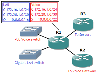
How does this work, and more importantly, why would you need it? Well, it is useful to provide complete separation of networks on the same router, so this router can be shared between different services, departments or clients. For example the following network:
VRF

Say you have to design an office, with desks and IP Phones. You already have one gigabit switch on stock, and the budget allows a 100 Mbps PoE switch. The manager insists on gigabit connections towards the desktops, and he insists that the voice network and data network are completely separated, with voice using static routes and the LAN using dynamic routing. However, you only get one router for the office itself. (This wouldn’t be good redundant design, that aside.) A good choice here is to connect all IP Phones to the PoE switch and all desktops to the gigabit switch, and connect both to the router. But since complete separation is needed, you can’t have any routing between the two. This is where VRF comes into play.

I’ll explain while showing the configuration. First, define VRF instances. Since there needs to be separation between IP Phones and desktops here, I’ll make two instances: VOICE and LAN.

router(config)#ip vrf VOICE
router(config-vrf)#exit
router(config)#ip vrf LAN
router(config-vrf)#exit

This separates the router into two, logical routers. Actually three instances, the default instance is still there, but it’s best not to use that one since it gets confusing. Next is assigning interfaces to their VRF. Let’s assume the PoE Voice switch is connected on Gigabit 0/0, and the gigabit switch on Gigabit 0/1. On Gigabit 0/2, there’s an uplink to the server subnets, and on Gigabit 0/3, there’s an uplink to the voice gateway.

R1(config)#interface g0/0
R1(config-if)#ip vrf forwarding VOICE
R1(config-if)#ip address 172.16.1.1 255.255.255.0
R1(config-if)#no shutdown
R1(config-if)#exit
R1(config)#interface g0/1
R1(config-if)#ip vrf forwarding LAN
R1(config-if)#ip address 172.16.1.1 255.255.255.0
R1(config-if)#no shutdown
R1(config-if)#exit
R1(config)#interface g0/2
R1(config-if)#ip vrf forwarding LAN
R1(config-if)#ip address 172.20.1.1 255.255.255.252
R1(config-if)#no shutdown
R1(config-if)#exit
R1(config)#interface g0/3
R1(config-if)#ip vrf forwarding VOICE
R1(config-if)#ip address 172.20.1.1 255.255.255.252
R1(config-if)#no shutdown
R1(config-if)#exit

You may have noticed something odd here: overlapping IP addresses and subnets on the interfaces. This is what VRF is all about: you can consider VOICE and LAN as two different routers. And one router will not complain if another router have the same IP address, unless they’re directly connected. But since VOICE and LAN do not share interfaces, as odd as this may sound, they are not connected to each other.

To further demonstrate the point, let’s add a static route to the VOICE router, and set up OSPF on the LAN router:

R1(config)#ip route vrf VOICE 10.0.0.0 255.255.252.0 172.20.1.2
R1(config)#router ospf 1 vrf LAN
R1(config-router)#network 0.0.0.0 255.255.255.255 area 0
R1(config-router)#passive-interface g0/0
%Interface specified does not belong to this process
R1(config-router)#passive-interface g0/1
R1(config-router)#exit

OSPF routing is also set up on router R3, towards the server subnets. Note that R2 and R3 do not need to have VRF configured. To them, they are connecting to the router VOICE and LAN, respectively. Also, when in the OSPF configuration context, I can’t put the Gigabit 0/0 interface in passive, as it’s not part of the LAN router.

And now the final point that clarifies the VRF concept: the routing tables.

R1#show ip route vrf VOICE

Routing Table: VOICE
Codes: C – connected, S – static, R – RIP, M – mobile, B – BGP
D – EIGRP, EX – EIGRP external, O – OSPF, IA – OSPF inter area
N1 – OSPF NSSA external type 1, N2 – OSPF NSSA external type 2
E1 – OSPF external type 1, E2 – OSPF external type 2
i – IS-IS, su – IS-IS summary, L1 – IS-IS level-1, L2 – IS-IS level-2
ia – IS-IS inter area, * – candidate default, U – per-user static route
o – ODR, P – periodic downloaded static route

Gateway of last resort is not set

172.16.0.0/24 is subnetted, 1 subnets
C       172.16.1.0 is directly connected, FastEthernet0/0
172.20.0.0/30 is subnetted, 1 subnets
C       172.20.1.0 is directly connected, FastEthernet2/0
10.0.0.0/22 is subnetted, 1 subnets
S       10.0.0.0 [1/0] via 172.20.1.2

R1#show ip route vrf LAN

Routing Table: LAN
Codes: C – connected, S – static, R – RIP, M – mobile, B – BGP
D – EIGRP, EX – EIGRP external, O – OSPF, IA – OSPF inter area
N1 – OSPF NSSA external type 1, N2 – OSPF NSSA external type 2
E1 – OSPF external type 1, E2 – OSPF external type 2
i – IS-IS, su – IS-IS summary, L1 – IS-IS level-1, L2 – IS-IS level-2
ia – IS-IS inter area, * – candidate default, U – per-user static route
o – ODR, P – periodic downloaded static route

Gateway of last resort is not set

172.16.0.0/24 is subnetted, 1 subnets
C       172.16.1.0 is directly connected, FastEthernet0/1
172.20.0.0/30 is subnetted, 1 subnets
C       172.20.1.0 is directly connected, FastEthernet1/0
10.0.0.0/16 is subnetted, 1 subnets
O       10.0.0.0 [110/2] via 172.20.1.2, 00:04:04, FastEthernet1/0

Different (logical) routers, different routing tables. So by using VRF, you can have a complete separation of your network, overlapping IP space, and increase security too!