Tag Archive: Troubleshoot


Disclaimer: the logs are taken from a production network but the values (VLAN ID, names) are randomized.

Recently, I encountered an issue on a Campus LAN while performing routine checks: spanning tree seemed to undergo regular changes.

The LAN in question uses five VLANs and RPVST+, a Cisco-only LAN. At first sight there was no issue:

BPDU-Trace1

On an access switch, one Root port towards the Root bridge, a few Designated ports (note the P2P Edge) where end devices connect, and an Alternative port in blocking with a peer-to-peer neighborship, which means BPDUs are received on this link.

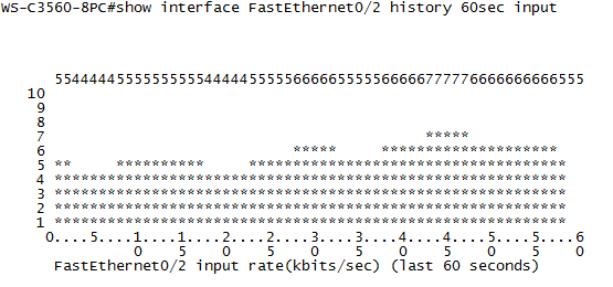
There is a command that allows you to see more detail: ‘show spanning-tree detail’. However, the output from this command is overwhelming so it’s best to apply filters on it. After some experimenting, filtering on the keywords ‘from’,’executing’ and ‘changes’ seems to give the desired output:

BPDU-Trace2

This gives a clear indication of something happening in the LAN: VLAN 302 has had a spanning-tree event less than 2 hours ago. Compared to most other VLANs who did not change for almost a year, this means something changed recently. After checking the interface on which the event happened, I found a port towards a desk which did not have the BPDU Guard enabled, just Root Guard. It was revealed that someone regularly plugged in a switch to have more ports, which talked spanning-tree but with a default priority, not claiming root. As such, Root Guard was not triggered, but the third-party switch did participate in spanning-tree from time to time.

Also, as you notice in the image, VLAN 304 seemed to have had a recent event to, on the Alternative Port. After logging in on the next switch I got the following output:

BPDU-Trace3

Good part: we have a next interface to track. Bad news: it’s a stack port? Since it’s a stack of 3750 series switches, it has stack ports in use, but the switches should act as one logical unit in regards to management and spanning-tree, right? Well, this is true, but each switch still makes the spanning-tree calculation by itself, which means that it can receive a spanning-tree update of another switch in the stack through the stack port.

Okay, but can you still trace this? You would have to be able to look in another switch in the stack… And as it turns out, you can:

BPDU-Trace4

After checking which stack port connects to which switch in the CLI, you can hop to the next one with the ‘session’ command and return to the master switch simply by typing ‘exit’. On the stack member, again doing the ‘show spanning tree detail’ command shows the local port on which the most recent event happened. And again the same thing: no BPDU Guard enabled here.


I recently got confronted with a difficult problem, in which I was unable to find what was the issue. Nevertheless it’s something most network engineers will be confronted with eventually. I can take no credit for the solution though, a colleague solved it (congrats, G).

The problem
The problem is as following:

Throughput

  • Client PC A, behind a WAN link, experiences a slow file transfer rate when uploading to server C. Speed: 1,88 MB per second (MBps).
  • From A to server D, uploading is fast, at 21,43 MBps.
  • Local PC B experiences great uploading speeds towards both servers: 26,08 MBps to C, 108,72 MBps to D.
  • Downloading on PC A from both server C and server D goes reasonable fast as well: 7,06 MBps for both.

At first sight, this is just not logical: no single component can be isolated to be the cause of the problem: the WAN link works fine towards server D and server C works fine when approached locally. On top of that, it’s only uploading to server C that is slow, downloading is faster.

Let’s start simple and look for bottlenecks. Testing shows the WAN line is capable of 200 Mbps throughput. A continuous ping from PC A to both servers averages to 8,30 ms, with little jitter. A similar continuous ping from PC B to the servers gives 0,60 ms. Vice versa, from servers to clients, it’s the same: 0,60 locally, 8,30 over the WAN link. All internal links at both the remote site and the main site use gigabit.

So the biggest bottleneck is the 200 Mbps WAN line. 200 divided by 8 gives 25 MBps. It roughly explains the speed from PC A to server D, but that’s about it. So what is causing it? Taking captures of the transfer (PC A to server C) reveals nothing at first sight:

SMB-1And that for gigabytes of transferred data. Never a lost packet, never an event, just the seemingly endless data-data-ack, data-data-ack,… But, let’s take a closer look at an interesting parameter:

SMB-2TCP Window, negotiated at 17kB. Would this differ for the other transfers? Let’s look at the transfer from PC A to server D:

SMB-33100kB! And when looking at the downloads from the servers on PC A, these both show 64kB. And they both have the same throughput. Now, a pattern is starting to emerge.

The explanation
Indeed, TCP Windowing becomes an important factor over WAN lines. Windowing determines how many packets of data can be sent to the receiver before an acknowledgement is needed. The bigger the window, the more packets can be sent before a return packet is needed. And the sender will not start sending more data before that acknowledgement is received. In a very low latency environment, this is barely noticeable: with 0,60 ms round-trip-time (RTT) and a TCP window of 17 kB, the sender needs to wait 0,60 ms every few packets (two in this case). Over the WAN link, it will need to wait 8,30 ms every two packets for the return packet. At a TCP window of around 3100kB, dozens of packets can be sent before a return packet is needed. Take for example 100 packets for each ACK, that would be 8,30 ms extra time for the single return packet, while an ACK every two packets over the WAN link for 100 packets would mean 415 ms of extra time, waiting for the ACK packets.

This can be put into a formula: TCP Window in bits divided by the round-trip-time in seconds. Source: http://en.wikipedia.org/wiki/TCP_tuning
This gives the following results:

TCP ThroughputThis comes very close to the test results! TCP Window and latency are used to calculate throughput. The Max throughput is the slowest of both Throughput and link speed (you can’t transfer files faster than 200 Mbps over the WAN link). Data throughput is the Max throughput minus 10 percent: this is to take into account the overhead from the headers (frame header, IP header, TCP header). The actual payload throughput is then converted to MBps (divided by eight) to give the final result.

The solution
The solution to this particular situation is checking for the TCP Window size parameters on the server C. With any luck these can be changed. Server C also didn’t rewindow (sending an ACK with a new TCP Window value) during the transfer, so it never became faster. Server D, while starting with a rather low window size, did rewindow, scaling up to 3100kB eventually. Of course, packet loss wasn’t taken into account int this scenario. Should there have been packetloss, server D probably wouldn’t have rewindowed up to 3100kB and might even have had to choose lower values than the one it started with.

TCP Windowing issues can be a lot of things, among which the following:

  • Settings on the receiving host TCP/IP stack, depending on the operating system: both starting window and the ability to rewindow.
  • Host parameters such as CPU and memory usage, disk I/O,… If the receiving host cannot keep up with the rate at which data is received, it will not rewindow to a higher value. After all, the received data has to be stored in RAM, processed, and written to disk. If any of these resources is not available, throughput will be limited.
  • Packet loss on the connection leads to missing data for which no ACK is sent. Throughput will not increase, or even go down as packet loss increases.

This concludes troubleshooting for now. The upcoming series of blog posts will be more theoretical and cover the OSI layer in greater detail. Stay tuned!

Syslog
Local logging is covered in Part I, but a device can only hold a certain amount of data. Centralized logging for easier access, correlation and historical tracking is something a good network needs.

Configuring remote syslog is a fairly easy process:

Switch(config)#logging host <ip-address>

That’s it. Of course, many extra options are possible:

  • ‘vrf vrf‘ behind the command to define the management/logging vrf to use.
  • ‘transport udp port port‘ behind the command to change the default port of 514. You can also use TCP here, but I don’t see the advantage as this will not save the logs in case of network issues.
  • ‘logging source-interface interface‘ can be used to define the source interface. A loopback can be useful if it’s a router with multiple interfaces, so the device always has the same IP address on the logging server.
  • ‘logging trap 0-7‘ to define the level of messages to send to the syslog server.

As a syslog server, many free and commercial ones are available. For a simple lab or home setup, I’m using tftpd32 (and tftpd64 for 64-bits systems). A very useful tool, and the TFTP function can also be used to upload IOS files to Cisco devices.

Syslog

Log optimization
Great, now logging works, but what further tweaks can be added? Quite a few, but I’m just going to describe the three things I find most useful.

First, it’s possible to log commands configured in the switch using the following configuration:

Switch(config)#archive
Switch(config-archive)#log config
Switch(config-archive-log-cfg)#logging enable
Switch(config-archive-log-cfg)#hidekeys
Switch(config-archive-log-cfg)#notify syslog contenttype plaintext
Switch(config-archive-log-cfg)#end

From now on, logging shows which user typed which command. Useful for an audit trail and seeing what went wrong during configuration.

Second, a link up/down event generates a severity 3 log message, but not every interface is equally important, and in an office environment a lot of these events may be generated during the day. This can be changed on a per-interface basis:

Switch(config-if)#logging event link-status

It’s also possible to toggle STP, PoE and DTP events. By default, they are all active, but ‘no’ in front of the command disables it. This way, logging and alerting of just the important ports becomes possible.

And last: when logged in through the console at a default speed of 9600 bps, it’s possible to become overwhelmed by the many logging messages. It can be rate-limited, with exceptions for certain severity levels, e.g.:

Switch(config)#logging rate-limit console 3 except 1

This logs a maximum of three messages per second towards the console, with exception of severity 1 alerts and up, who will always show.

When I was studying for CCNA and even CCNP, I never gave that much attention to logging features on a device. Although I got through the certifications without it, I realize now that without proper logging, troubleshooting complex issues after they happen is just plain impossible. Logging is mandatory, otherwise you might very well end up with a network that goes down at seemingly random intervals, unable to figure out what is causing it.

Logging
Some basics first: for logging, there are 8 different levels of events, to differentiate between different severity levels (RFC 5424 for details). These are the levels:

  • 0       Emergency: system is unusable
  • 1       Alert: action must be taken immediately
  • 2       Critical: critical conditions
  • 3       Error: error conditions
  • 4       Warning: warning conditions
  • 5       Notice: normal but significant condition
  • 6       Informational: informational messages
  • 7       Debug: debug-level messages

I’ve never seen a level 0 event in logging, as ‘the system is unusable’ in reality means the device has crashed. Below some example logs:

Dec 16 16:05:18.438: %SSH-5-ENABLED: SSH 2.0 has been enabled
Dec 16 17:38:50.518: %LINK-3-UPDOWN: Interface FastEthernet0/2, changed state to up
Dec 16 17:41:11.725; %SYS-6-CLOCKUPDATE: System clock has been updated

First the notice that SSH 2.0 has been enabled, followed by ‘error’ level of a link state change and an informational message that the system time has been updated. Note that these messages have a timestamp: for proper logging, the device clock needs to be accurate. Be sure to look into the possibilities of NTP.

When you’re connected by console, you can see the logging messages in real-time. By default, through Telnet or SSH, you don’t. The command ‘terminal monitor’ enables this behavior. Next to this, there’s also the possibility to choose the logging level: ‘logging console 0-7‘ for the console and ‘logging monitor 0-7‘ for Telnet and SSH. So ‘logging console 3’ will only show level 3 events and up: link state changes, security issues (usually level 2, e.g. port-security),… but no clock updates.

But this is only real-time monitoring. To have some history, switches have a local log buffer: ‘logging buffered size 0-7‘, where size is the size of the log buffer in bytes. The bigger, the more history, but also the more RAM usage, so think before typing huge numbers. If configured, ‘show logging’ shows you the different logging levels configured, followed by the contents of the log buffer. Filtering can be useful here, e.g. ‘show logging | include 0/2’ to show all events related to interfaces with 0/2 in the name.

Now we’re getting somewhere: logs, present on the device, with timestamps. Enough to SSH to a device after a mayor event in the network and see what happened. But what if the device reboots? Everything is stored in RAM. For this there’s two options: syslogging to a remote server, and storing messages on the flash. Syslogging will be discussed in part II, but it’s not fool-proof since syslog uses UDP (port 514) and during mayor network events, those UDP packets may get lost. Storing logging on flash can be done with ‘logging file flash:log.txt size 0-7‘, where ‘log.txt’ is a file name, size is the maximum size on flash (be careful to leave room for other critical files such as IOS and startup-config) and again followed by a severity level. Because it is flash, it’s best not to overuse it and set the level to error (3) or critical (2). The file can be seen with ‘more log.txt‘, even after a reboot. Useful to recover some data from a crashed device.

Utilization
Logs are one thing, but some things aren’t visible in logs. Most important one is CPU utilization: if something is clogging the CPU (e.g. a broadcast storm), there may not be any logging events, and even if there are, they may not point in the right direction, such as spanning-tree topology changes, giving the impression a link went down somewhere while it’s not the case. Three great commands:

  • show proc cpu sorted: show which process is taking most CPU.
  • show proc cpu | include CPU: quickly shows CPU usage. You can repeat this command quickly a few times, even when the device is under load, due to the single line of output.
  • show proc cpu history: draws an ASCII graph of CPU usage. Less relevant than the other too, but admit it: a lot cooler.

The following configuration is something I wouldn’t recommend, but can be useful on a single switch (SOHO environment) without dedicated logging infrastructure: interface utilization graphs on the switch. There can be enabled with the ‘history bps’ (bytes per second) or ‘history pps’ (packets per second) command under interface configuration mode. After enabling, you can see an ASCII graph of the interface with ‘show interface interface history’:

IntUtiGraph

This is just a 60 second graph, but just like with CPU utilization, it can show up to three days.

Static host entries for troubleshooting.

Something a bit more simple, yet sometimes very effective: using static host entries. Once again, I have unstable internet at home and it disconnects from time to time. While the other users in my house have some basic knowledge about networking, it’s not their thing, so it’s limited to ping and ipconfig.

The topology in my house does not make it easier for them: a computer connected to a managed switch, which then connects to an ISP modem with build-in router functionality (NAT, DHCP). It’s not always clear what is the cause: sometimes the internet goes down, but the modem/router has also crashed at times, and at one time the cable towards the switch failed and had to be replaced. While I can quickly see where the problem is depending on what I can ping, other users don’t remember all those IP addresses.

Until I got the idea to create static host entries. These are like DNS entries, but configured on a local computer so it’s not dependent on the network to use them, and simple entries can be made for devices that do not have DNS entries.

In Windows, these entries can be made in the hosts file, which you can find in C:\Windows\System32\drivers\etc as a file without extension. It can be opened in notepad and per line an entry can be added, e.g. ‘192.168.1.1 modem’ and ‘192.168.1.2 switch’. In Linux, this is the /etc/hosts file, and in MAC OSX, it’s /private/etc/hosts . After modifying it, troubleshooting becomes much more clear:

PingSwitch

The switch can still be reached, and a ping to ‘modem’ shows if the modem is still alive. Simple and effective.

Of course this is mainly useful at home, although this can be interesting for a remote office as well. It makes troubleshooting with end users easier, as no IP addresses have to be dictated through the phone or looked up in documentation.

Traffic captures: tips and tricks.

I have been planning a completely different blog post for over a week now, but I’m currently not advancing in my research. Instead, due to the many experiments, I’ve become better at capturing traffic.

Tools of the trade: Wireshark (Windows) and tcpdump (Unix). While tcpdump works on the command line and is very lightweight, Wireshark comes with a lot more options and a GUI. The two are compatible: capture files saved with tcpdump can be opened in Wireshark.

TCPdump parameters
This very simply tool is usually included by default on a Unix platform (Linux, OpenBSD, vendor systems running on a Linux kernel, …). It can have many parameters, of which I’ll list the most useful here:

  • -n – Makes sure no name resolving of addresses, and conversing of port names (e.g. 80 to www) is done. Since you’re probably troubleshooting on layer 2 and 3, it’s easier to see the actual numbers.
  • -i int – Specifies an interface to capture on. If you don’t specify it in a recent Linux kernel, it will take the first non-loopback it finds. However, when networking, devices you encounter often have multiple interfaces.
  • -s length – Sets the length that packets will be captured. By default only the first bytes are captured. Setting this value to 1514 will allow you to capture all packets on an Ethernet interface completely, which is handy for the -w option below.
  • -w file – Writes the capture to a file instead of showing it on-screen. If you specify it as a *.pcap file, it can be opened in Wireshark later on!

As an example of the above, ‘tcpdump -n -w /var/log/ethertest.pcap -i eth0’ will do a packet capture on interface eth0 and write the information to the ethertest.pcap file, without doing any name resolution. To stop a capture, press ‘Ctrl+C’. A more complete list of parameters can be checked here.

TCPdump filters
Apart from the parameters, filters are possible. Below a few handy ones:

  • host ip – Only capture packets that originate from or are destined to a certain IP address. The most common mistakes you can make with this filter are forgetting there’s NAT somewhere involved, so you don’t see anything because you’re filtering on an IP address that’s no longer present in the packets, or something is using IPv6 though dual stack and while you’re capturing on the right interface, nothing shows because you’re filtering on IPv4.
  • net prefix – Only capture traffic from or to a certain subnet, e.g. 192.168.4.0/23.
  • port number – Capture traffic with a certain port number, both UDP and TCP. Usually this is clear enough as there’s rarely both a UDP and a TCP stream on an interface with the same port number. Also counts both for destination and source port number.
  • icmp – ICMP traffic only. Great to see if your pings go through somewhere.
  • vlan number – Only frame that have an 802.1q header with the matching VLAN number will be captured. This option is very important on trunk links in combination with ‘-w’, as I’ve noticed tcpdump doesn’t always write tagged frames correctly to a file unless this filter is applied.
  • ‘not’, ‘and’, and other booleans – These allow you to negate things and make combinations.

Some examples explain these filters:
‘tcpdump -n -i eth0 not port 22’: capture all traffic except port 22 (useful when you’re connected through SSH on the same interface).
‘tcpdump -n -i eth0 host 10.0.5.3 and host 10.2.3.14’: capture all traffic between those two IP hosts.

Wireshark
Wireshark has some extra functionality compared to tcpdump, but tcpdump filters are present as well. Under ‘Capture’, ‘Options…’ you can define a capture filter, which uses the exact same parameters as tcpdump. Using ‘not port 3389’ here for example is useful if you’re trying a capture on a remote computer. You can also use a filter on all captured frames to show only those interesting to you. Difference with the pre-capture filter is that this filters out what you see, but not what is captured, which is useful when taking a raw capture to examine later. Some important ones:

  • icmp: Just ICMP traffic.
  • udp.port and tcp.port: TCP or UDP port number. Unlike tcpdump’s ‘port’ you can differentiate between UDP and TCP here.
  • ip.dst and ip.src: Source and destination IP addresses.
  • eth.dst and eth.src: Source and destination MAC addresses.
  • tcp.stream: Filter out one single TCP stream. Useful to follow a connection in a sea of frames.

Booleans can be used just like with tcpdump, and to define a variable, use ‘==’, e.g. ‘ip.dst == 10.0.0.1 and not icmp’  will show all traffic towards 10.0.0.1, except ICMP packets. Next to ‘==’ (equal to), variables can also be ‘>’ (greater than), ‘>=’ (greater or equal than), ‘!=’ (not), ‘<‘ (smaller than) and ‘<=’ (smaller or equal than).

Wireshark’s extra functionality is due to the graphical element: under ‘Statistics’ you can use ‘IO Graphs’ to show bandwidth usage during the capture. This helps visualize the traffic patterns: are there sudden bursts of traffic, or just a steady flow? Here too you can filter.
Under the same ‘Statistics’ there’s also ‘Conversations’, which makes a list of all captured traffic flows. You can sort this list to show the connections that use the most bandwidth. Very useful to find what’s causing unexpected bandwidth usage.

SPAN ports
Optimizing the filters to capture data is one thing, but optimizing the replicated data to capture on a SPAN interface can be beneficial too. A basic SPAN session on the same switch is set up as following:

Router(config)#monitor session 1 source interface G1/0/1
Router(config)#monitor session 1 destination interface G1/0/5

There are however a few tweaks possible. First, capturing on a trunk link is possible, and it’s possible to filter out only the required VLANs using the ‘monitor session 1 filter vlan vlan-list‘. A good use of this is when trying to capture traffic on a few VLANs on a gigabit trunk link, while the SPAN port is a 100 Mbps port. By filtering only the needed VLANs less traffic will be replicated and the 100 Mbps link will not saturate as quickly.

Second, while a SPAN port replicates most traffic, it does not replicate switch control frames like BPDUs and CDP frames. You can force the replication of these frames using the ‘monitor session 1 destination interface G1/0/5 encapsulation replicate’ command. A good use for this is checking why an IP Phone will not come online, for example.

The above are all just small tips and tricks, but together they make troubleshooting something a lot clearer.

CCNP certified!

Yes, I passed TSHOOT two days ago! I just waited to post here until I received the confirmation mail.

And now I’d like to say a lot, but there’s the NDA of course. I will say the following to those attempting CCNP: if you’ve mastered SWITCH and ROUTE with practice labs like I did, TSHOOT is a walk in the park. Just make sure you know a lot of ‘show’ commands and try to troubleshoot everything as logical as possible.

I’m very happy now, I can end 2011 with a goal completed. Up next: who knows? I’m still considering CCIE, but given what amount of knowledge I’ll need to learn, I’m not going to have a lot of time for it next year. But I’ll keep on learning something, that’s for sure. Not standing still here.

Thanks to all who supported me!

TSHOOT booked!

I decided to go for it and book my TSHOOT exam for next week, Tuesday december 20.

Do I feel ready? I have no idea. This exam is going to be more practical compared to ROUTE and SWITCH, so it’s going to be different. Luckily, thanks to my new job I feel confident about layer 2 troubleshooting, since that is what I’ve been doing mostly in the past weeks. A good thing really, because originally, layer 3 stuff like routing protocols was easier for me than layer 2.
In the past week I’ve set up a SPAN port, did troubleshooting on port channels, had to calculate PoE budgets on access-layer switches, checked VLAN usage and spreading, and so on. The SPAN port was one of the bigger challenges, as I had to do it on a Nexus, which is a whole different beast at times compared to a Catalyst switch. Perhaps more on that in an upcoming blog post.

Reviewing IPv4 routing hasn’t posed any problems so far. Even reviewing NAT again went easy. IPv6 had a surprise for me (note: redistributing something into RIPng requires a metric to be set), but no big problems either.

I’m putting more emphasis on ‘debug’ commands now. I’ve hardly used them so far, but I will need them on the exam. I was able to find out a typo in my EIGRP authentication keys with it in my lab practice. Together with the ‘show’ commands they’re probably my key to passing it.

So no new blog post until I’ve done the exam. I hope it’ll be a very happy one.

Testing a new toy: the Flukes.

Fluke devices.

My colleagues were kind enough to let me borrow a Fluke Linkrunner Pro and a Fluke Service Provider Assistant for the weekend , to let me get familiar with them. Since this kind of gear is unaffordable for a home lab, I took the opportunity to do some tests on my equipment.

The Linkrunner Pro (left on the picture) can provide several details about a network connection. It shows the cable length of any Ethernet cable you connect it to, even if that cable isn’t connected on the other end! It also indicates when one or more of the eight internal wires are damaged, and detects PoE, again telling what is delivered through which wire.
Some initial tests indicated the wire from my lab to my ISP uplink is 28 meters, my 3560 uses PoE mode A, and a 4 meter long cable I patched myself had one disconnected pair.

The Service Provider Assistant can be connected both by Ethernet and an SPF module for fiber connections. It can do ping, tracert, perform jitter tests, and in combination with the Linkrunner Pro it can do a throughput test. This is a useful test: you connect the Linkrunner on one end, give it an IP and set it to ‘reflect’, and on the other end of the network, you connect the SP Assistant and let it generate traffic to the Linkrunner’s IP, up to 1 Gbps.

First thing I wanted to know was whether my 2970 switch could really reach gigabit speeds. I connected both devices to the switch, gave them an IP in the same subnet, and started a throughput test. I let it run for 10 minutes because the switch only shows average throughput over 5 minutes. I did several tests, using different ports, and each time ended up with an effective throughput of 980-985 Mbps, using an MTU of 1518. Not exactly one gigabit, but 98.5% is close enough. I also monitored CPU during the test, which averaged at 4%, about the same when completely idle, proving that switching is done in hardware on the device.

Next, I connected the devices on the 3560 switch in different subnets, with the 3560 providing the routing using SVIs. Strangely, the Service Provider Assistant was recognized as an unsupported class 7 PoE device, and after a second automatic negotiation received class 0 PoE power, 15.4 Watt. The device did not charge from it however, and contrary to the Linkrunner Pro it doesn’t have any PoE diagnostics, leaving me in the dark about the meaning of it. Most likely it needs an 802.3at capable PoE device to be able to charge. (If you’re not following the PoE talk, I’ve explained things here.)
The 3560 has 100 Mbps ports, and the throughput test between two ports in different VLANs (and subnets) gave a result of 97 Mbps. CPU idled at 5%, because routing is done in hardware using Cisco Express Forwarding or CEF, a multi-layer switching technology. However, when forcing the routing to software with the ‘no ip route-cache’ command on the SVIs, things changed slightly. Throughput was still 97 Mbps, but the CPU went up to 8%, with a few peaks that weren’t there before. That 3% difference isn’t much, but I’m just congesting two ports. Following this logic, 24 ports routed in software at 100 Mbps should use about 40% CPU, and 48 ports 75% CPU, not including other processes such as routing protocols, spanning-tree, access-lists,… This makes clear that routing in hardware can really make a difference by increasing switch stability.

Finally, I also tested frames with 64 bytes of payload instead of the MTU of 1518. While supposedly this takes a higher toll on the switch’s resources compared to large frames, I didn’t note any differences in my simple tests.

It’s friday again, facing the weekend. The good news is: this is my last day at my current job, starting Monday I’m officially a data center network engineer (same employer). Happy that my studies have paid off! On the other hand, I bragged about my studies, so I now better finish off that TSHOOT exam and prove my worth.

I haven’t blogged a lot lately, but I did make a contribution to the networking-forum.com with a blog post. Special thanks to Steve (the owner) for making this possible.

Finally I’ve had some time to work in my lab again, but I couldn’t test anything I wanted to test. So far I’m unable to bridge an interface (loopback of physical) on Ubuntu with GNS3. I need more knowledge to properly set up my IP Phones for testing, a RADIUS server would be nice, and I’m currently negotiating a new device for my lab but that’s taking longer than expected (spoilers…). So all in all, I’m spending more time configuring operating systems than doing actual labs. Part of the experience I suppose.

I did learn a few things these weeks that may come in handy:

  • When setting up larger OSPF networks, also configure a router-id. Chance that a duplicate id is formed using a physical interface ip is small, but the ‘show ip ospf database’ command makes no sense if you can’t recognise which router sent which LSA.
  • Windows 7 will show when 802.1x authentication fails. Very useful. Ubuntu gives a lot more options for 802.1x, but doesn’t give that much output.
  • Without a config to work with, an IP Phone will not allow communication between the daisy-chained computer and the switchport. I’m going to need a tftp config server, and learn some voice.
  • I’m going to have to learn SSLVPN. I got to test one briefly and it’s above my level of understanding. Luckily I’ve got a CCNP Security Secure 642-637 eBook, purchased through a Deal of the Day by CiscoPress.

And finally, looking at my last blog posts, I like making lists. Seems the best way for my mind to absorb knowledge, and I assume many people will agree on that.