Tag Archive: VLAN


On this blog I’ve often covered Private VLANs: how to configure them, work around them and deploy them in a larger network. Yet it’s rarely that you see an actual Private VLAN in a design. Part of the problem is covered in the article about deployment over multiple switches: you can’t connect a trunked device such as a firewall to it. Although the Nexus 7000 provides a solution, that doesn’t make it much easier (or cheaper).

Another important reason is that few are willing to take the risk to deploy a VLAN where hosts cannot communicate with each other, as this is usually the reason hosts are put in the same VLAN in the first place. There’s the hesitation because it would introduce complexity or limit scalability, as new servers later on may need to communicate in the same subnet after all.

So where would it be beneficial and with low risk to use a Private VLAN? Actually quite a few places.

E-commerce
AppFlowDMZ

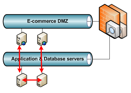
Say you have an internet-facing business with e-commerce websites where anyone can log in, create an account, or do a purchase. A compromised e-commerce server in the DMZ means immediate access to the entire DMZ VLAN. This VLAN has the highest chance of being compromised from the internet, yet the servers in it rarely need to speak with each other. In fact, if properly designed, they will all connect to backend application and/or database servers that on their turn communicate with each other. This way the e-commerce data is synchronised without the DMZ servers requiring a connection to each other.

Stepping Stones
SteppingStones

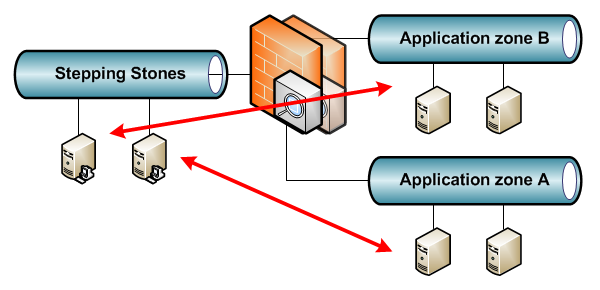
Some environments have a VLAN with Stepping Stone servers where users can log on to with pre-installed tools to access confidential resources. Access from one Stepping Stone server to another is not needed here. Sometimes it’s even not desired as there may be a Stepping Stone per application, environment or third-party.

Out-of-Band
A modern rackserver has an out-of-band port to a dedicated chip in the server that can power off and on the server, and even install the OS remotely. For example, HP iLO. Typical here is that the out-of-band port never initiates connections but only receives connections for management, usually though the default gateway. This makes for a good Private VLAN deployment without issues.

Backup
BackupVLAN

Similar to out-of-band, some environments use a dedicated network card on all servers for backup. This introduces a security issue as it’s possible for two servers in different VLANs to communicate without a firewall in between. Again a Private VLAN can counter this. Somewhat unusual in the design is that it’s best to put the servers taking the backup in the promiscuous VLAN, so they can communicate with all servers and the backup VLAN default gateway, and put the default gateway in an isolated VLAN, preventing any other server from using it.

Campus – Wired guests
Similar to the Stepping Stones: guests can access the network through a firewall (the default gateway) but don’t need to access each others computers.

Campus – Wireless APs
In a WLAN deployment with a central controller (WLC), all the Lightweight APs do is connect to the controller using the subnet default gateway. Any other services such as DHCP and DNS will be through this default gateway as well.

Campus – Utilities
Utilities such as printers, camera’s, badge readers,… will likely only need the default gateway and not each other.

Where not to use PVLANs
This should give some nice examples already. But for last, a couple of places where not to use Private VLANs:

  • Routing VLANs: unless you want to troubleshoot neighborships not coming up.
  • VLANs with any kind of cluster in it: still doable with community VLANs for the cluster synchronisation, but usually better off in their own VLAN.
  • User VLANs, VOIP VLANs and the like: VOIP and videoconferencing may set up point-to-point streams.
  • Database server VLANs: not really clusters but they will often require access to each other.

Using MPLS on the WAN is a great way for multi-customer WAN connectivity, but so far it’s all layer 3. Layer 2 technologies like Ethernet over MPLS (EoMPLS) exist, but I have  little experience with it so far, so I’m not covering it (yet).

Instead, something else: layer 2 WAN services. Let’s assume you need to transport layer 2 VLANs from multiple customers over WAN links. Using a dedicated line per customer makes configuration easy, but it’s not cost-efficient. Instead, you want to use a mesh of switches that transport the customer data. The concept is simple enough, but it has some practical limitations: you can’t have overlapping VLAN numbers between customers.

This is where Metro Ethernet switches step into the picture. In particular, I had the chance to work with a ME-3600X-24CX-M switch, and it’s something entirely different from a Catalyst switch.

ME-3600X-24CX-M

The difference is that this switch is made for MAN and WAN networks: it can run MPLS, supports VRF and has support for Ethernet Virtual Circuits (EVC).

EVC is a technology where you no longer use the 802.1q header of a frame only to specify to which network a frame belongs, but you use it for a number of different things, such as identifying a customer for example. It even allows multiple tags on a frame. Configuration of EVC is done on an interface (physical or port-channel), by making it a trunk, and the command ‘switchport trunk allowed vlan none’. Why this command? Because it makes the interface step out of its typical trunk mode and into EVC, after which service instances can be defined that match on 802.1q headers. An example configuration, where G0/1 and G0/2 are customer links and G0/3 is a shared WAN link:

Switch(config)#interface GigabitEthernet0/1
Switch(config-if)#switchport trunk allowed vlan none
Switch(config-if)#switchport mode trunk
Switch(config-if)#service instance 1 ethernet
Switch(config-if-srv)#encapsulation dot1q 100-200
Switch(config-if-srv)#bridge-domain 5010
Switch(config-if-srv)#exit
Switch(config-if)#exit
Switch(config)#interface GigabitEthernet0/2
Switch(config-if)#switchport trunk allowed vlan none
Switch(config-if)#switchport mode trunk
Switch(config-if)#service instance 1 ethernet
Switch(config-if-srv)#encapsulation default
Switch(config-if-srv)#bridge-domain 5020
Switch(config-if-srv)#exit
Switch(config-if)#exit

This seems complicated at first sight, but let’s look at the configuration lines one by one:

  • As said before, ‘switchport trunk allowed vlan none’ activates EVC.
  • ‘service instance number ethernet’ defines a policy, matching on 802.1q headers.
  • The ‘encapsulation dot1q 100-200’ makes that this service instance will be applied to all incoming frames with an 802.1q header between 100 and 200.
  • ‘bridge-domain 5010’ places these frames in a bridge domain. A bridge domain is like a VLAN, but it doesn’t use tags. All frames of the service instance are put in bridge domain 5010. All frames of the service instance on the next port are put in bridge-domain 5020. This way, even if there are overlapping VLANs, the differing bridge-domains keep them separated inside the switch.
  • ‘encapsulation default’ means anything not defined before. If it is the only service instance on the link, as in this case, it means every incoming frame.

So the configuration of the customer links makes sure the frames stay separated (in bridge-domains) even if there is a VLAN overlap. The shared WAN uplink is now as following:

Switch(config)#interface GigabitEthernet0/3
Switch(config-if)#switchport trunk allowed vlan none
Switch(config-if)#switchport mode trunk
Switch(config-if)#service instance 1 ethernet
Switch(config-if-srv)#encapsulation dot1q 10
Switch(config-if-srv)#rewrite ingress tag pop 1 symmetric
Switch(config-if-srv)#bridge-domain 5010
Switch(config-if-srv)#exit
Switch(config-if)#service instance 2 ethernet
Switch(config-if-srv)#encapsulation dot1q 20
Switch(config-if-srv)#rewrite ingress tag pop 1 symmetric
Switch(config-if-srv)#bridge-domain 5020
Switch(config-if-srv)#exit
Switch(config-if)#exit

Note there are two service instances, one per customer in this case:

  • Both instances refer to different bridge-domains, keeping the separation per customer.
  • Both match one 802.1q tag on incoming frames: 10 for bridge-domain 5010, customer G0/1, 20 for bridge-domain 5020, customer G0/2
  • ‘rewrite ingress tag pop 1’ means incoming frames will have their outer 802.1q tag removed.
  • Finally, the ‘symmetric’ keyword means that outgoing frames will have an 802.1q tag added: the one defined in the service instance.

This means the following: a frame entering from G0/1 will have a second 802.1q applied, VLAN 10, if it goes over the WAN link. Same for G0/2 towards the WAN link, only with VLAN 20. This means that if both customers send a frame with VLAN 100, the G0/1 frame will be sent out of G0/3 with inner 802.1q header 100 and outer header 10. The G0/2 frame will have inner header 100 also, but outer header 20. Separation between both customers is ensured, even with overlapping VLANs! A remote Metro switch on the other end of the link can use similar service instances again to remove the outer header and place each frame in its own bridge-domain.

Dot1q2

This is just one of the things possible with EVC. You can add 802.1q headers, remove them, but also translate them, by matching different headers on different interfaces in the same bridge-domain:

Switch(config)#interface GigabitEthernet0/4
Switch(config-if)#switchport trunk allowed vlan none
Switch(config-if)#switchport mode trunk
Switch(config-if)#service instance 1 ethernet
Switch(config-if-srv)#encapsulation dot1q 30
Switch(config-if-srv)#rewrite ingress tag pop 1 symmetric
Switch(config-if-srv)#bridge-domain 5030
Switch(config-if-srv)#exit
Switch(config-if)#exit
Switch(config)#interface GigabitEthernet0/5
Switch(config-if)#switchport trunk allowed vlan none
Switch(config-if)#switchport mode trunk
Switch(config-if)#service instance 1 ethernet
Switch(config-if-srv)#encapsulation dot1q 60
Switch(config-if-srv)#rewrite ingress tag pop 1 symmetric
Switch(config-if-srv)#bridge-domain 5030
Switch(config-if-srv)#exit
Switch(config-if)#exit

This configuration translates frames incoming on G0/4, VLAN 30, to frames tagged as VLAN 60 on G0/5. Again, the ‘symmetric’ keyword makes it work in both directions.

Dot1qTranslated

The switch does all of this in hardware forwarding, so gigabit bandwidth while forwarding and changing headers is possible. When headers are added, the MTU of the link may need to be increased though. And what if you want a layer 3 VLAN interface on the switch to manage it remotely? Can you enter through a link using EVC? Yes, you can: so far, I’ve used bridge domains above 4094, but if you define a bridge-domain below 4094, the VLAN of the same number will automatically be created on the switch, and its layer 3 interface is automatically part of that bridge domain. You do need to remove the 802.1q header(s) for incoming frames, as the frames need to reach the layer 3 interface ‘untagged’ internally. Assume you come in over the WAN link, outer header VLAN 30, inner header 10:

Switch(config)#interface GigabitEthernet0/3
Switch(config-if)#switchport trunk allowed vlan none
Switch(config-if)#switchport mode trunk
Switch(config-if)#service instance 3 ethernet
Switch(config-if-srv)#encapsulation dot1q 30 second-dot1q 10
Switch(config-if-srv)#rewrite ingress tag pop 2 symmetric
Switch(config-if-srv)#bridge-domain 50
Switch(config-if-srv)#exit
Switch(config-if)#exit
Switch(config)#interface Vlan50
Switch(config-if)#description Management
Switch(config-if)#ip address address subnetmask
Switch(config-if)#exit

As you can see, both 802.1q headers will be stripped off and the frame is placed in bridge-domain 50. This way it reaches VLAN interface 50. Other customers can’t reach this VLAN interface because they’re not part of the same bridge-domain.

Cisco support forums has a nice document explaining the concept, also together with MPLS. Be sure to check it out if you want to know more!

I’ve discussed Private VLANs before and I still consider them a useful technology. However, most mentions and implementations of PVLANs only use one switch, and it’s not clear what the interactions of PVLANs with other devices are.

PVLAN-Trunks

The above setup features three switches and a firewall, all connected through trunk links. SW1 and SW3 can use PVLANs, and SW2 can use VLANs but has no awareness of Private VLANs, as it’s a transit switch. The firewall acts as default gateway for all the VLANs, including the PVLANs (a real-world example would be an ASA 5510 here). The requirements of the setup are that an isolated port on one switch can’t talk with an isolated port on another switch, an isolated port on one switch can talk with a promiscuous port on another switch, it works over transit switches, and the trunk link can be used as default gateway. Will this scenario work? Let’s examine.

Cisco recommends to define both the isolated and promiscuous VLANs on all trunk links and transit switches. To remain consistent between switches, frames are always sent over trunk links tagged with the originating VLAN. A frame coming from an isolated VLAN will go over a trunk link tagged as the isolated VLAN. This way, the next switch knows it came from an isolated port and will only allow communication with either a promiscuous port or another trunk link that allows the isolated VLAN.

This logic solves the first requirements: the information of the origin port is carried over to the next switch, and PVLANs can work perfectly over multiple switches. Does this also include the unaware transit switch? Yes it does: it treats the PVLANs as just a VLAN and allows traffic over the trunk links. Of course, if the switch is not aware of Private VLANs, it’s not possible to configure access ports in those VLANs, isolated or promiscuous.

But how does return traffic behave? If a frame is sent from an isolated port to a promiscuous one (a default gateway), how does it return? It returns tagged as the promiscuous VLAN over the trunk links and can communicate to all ports: trunk , isolated and promiscuous ports. And this is where the flaw in the PVLAN design is: over trunk links, the switch expects return traffic to arrive over another VLAN. A ping from a device towards the default gateway goes over the trunks in the isolated VLAN and returns in the promiscuous VLAN. And a firewall with trunk links (e.g. an ASA) can’t handle this: it has no awareness of Private VLANs. It will send return traffic down the same VLAN, and once this arrives on the switch, the switch will think it’s a frame from an isolated VLAN access port and deny communication with all other isolated ports. Return traffic cannot reach the destination anymore.

In defence of  the ASA, not a single vendor has PVLAN awareness in firewalls or routers. And this cripples the technology in larger environments, as you’re constrained to use one access port per VLAN in a Private VLAN environment, and this doesn’t scale when dealing with many VLANs.

Update 13/03/2014: the test setup for this blog post did not cover MAC address learning so I missed a very important fact: non-PVLAN aware switches will flood traffic in the Private VLANs, as they will never learn the destination MAC addresses of traffic in the same VLAN. This will not scale. Thanks to the networking-forum.net members again for the nudge in the right direction!

Time to review something that has been very unclear to me from the beginning: Dynamic Trunking Protocol. First off, it’s a Cisco-only protocol, and let’s be honest, it has no real world uses except acting as a security risk. Second: most literature about it is in fact quite unclear, except the CCIE OCG so far, but even then I’m left with question marks.

So let’s go through the theory first, as this is usually the best way to start:

  • DTP sends special frames out of every switchport by default, which can be used to negotiate a trunk link, and negotiate the encapsulation (802.1q or Cisco-proprietary ISL).
  • The frames can either be ‘auto’, ‘desirable’, or ‘on’. While ‘desirable’ and ‘on’ actively try to negotiate a trunk, ‘auto’ only negotiates one when the other end is set to trunking.
  • The ‘switchport nonegotiate’ command prevents DTP frames from being sent.

Now, let’s see how it goes in practice.

Commands without effect
It’s never mentioned explicitly in any literature I’ve encountered so far, so I tested it just to be sure. The commands ‘switchport access vlan number‘ and ‘switchport trunk allowed vlan numbers‘ do not have any effect on DTP at all. Should the port become an access port, then the ‘switchport access’ command is used to define the VLAN, and the trunk allowed list is ignored. Should the port become a trunk, the trunk allowed list is used and the access VLAN is ignored. Same for ‘switchport trunk native vlan number‘, which is only used should the port become a trunk.

Default configuration
The default configuration of a Cisco switch is to send out DTP auto frames. This means no trunk link will be formed unless configured to do so. And here’s the security risk: if you leave a port in it’s default configuration, someone sending a DTP desirable frame can form a trunk and gain access to all VLANs. In case you’re thinking ‘Oh, this is highly theoretical’: it took me less than 30 minutes to find, download and install Yersinia on a Linux VM and send DTP frames to my home lab switch.

Commands with effect, and their changes
So what actually influences DTP? Two commands, it seems: ‘switchport mode’, and ‘switchport nonegotiate’. I’m listing my findings below, after trying all possible combinations on a switch:

  • Default configuration: DTP sends two frames every 30 seconds (a timer that can’t be changed): one untagged frame, one ISL encapsulated frame. Both are DTP ‘auto’ mode (status code 0x03). Since ISL has no concept of native VLAN and some (older) switches only support ISL, sending the second ISL frame makes sense for compatibility reasons. DTP also sends a DTP Type, which is a HEX code listing the supported encapsulation methods.
  • ‘switchport mode access’: no DTP frames are sent. At all. The ‘switchport nonegotiate’ does not make any difference.
  • ‘switchport mode trunk’: DTP frames are sent in mode ‘on’, with a status code of 0x81. Since you have to choose either ISL or 802.1q as an encapsulation method before you can make the port a trunk, DTP sends this parameter too: 0xa5 for 802.1q and 0x42 for ISL. Also, independent of the encapsulation chosen, DTP will again send two frames: one untagged, one ISL encapsulated.
    Note that this port will operate in trunk mode regardless of what the other end decides. The frames are sent to help the other end in negotiation and choosing the right encapsulation. A port with default configuration will convert to a trunk port when receiving these DTP frames.
    Using ‘switchport nonegotiate’ here stops the sending of DTP frames. Should this port connect to a port with default configuration now, it will still be a trunk, but the other and will stay an access port.
  • ‘switchport mode dynamic auto’: this is the default configuration and this line will not even show in the running config.
  • ‘switchport mode dynamic desirable’: again like the default configuration, the only difference being status code 0x04, and a trunk will actively form when a port running DTP is connected (no matter the other end’s DTP mode).

Another unexpected command which has effect is the ‘vtp domain name‘: I’ve researched that before.

Practical implications
So what’s best in practice to counter any unexpected behavior, and security risks?
In case of an access port, ‘switchport mode access’ is effective enough as it shuts down DTP on a port. ‘switchport nonegotiate’ is a redundant command, so it doesn’t matter whether it’s applied or not. Just defining ‘switchport access vlan number‘ without the matching ‘switchport mode access’ is a security risk.
In case of a trunk port, I would still recommend disabling DTP, so a static configuration with ‘switchport nonegotiate’ becomes mandatory.
And what if DTP somehow is required to run, can the risk be minimized? (This is theory, if someone requires DTP, you… try to stay calm.) Yes: ‘switchport trunk allowed vlan numbers‘ can be configured to only allow access to the default access VLAN, or even set to ‘none’. This command doesn’t become effective until a trunk is negotiated.
Last, the Nexus series doesn’t run DTP at all, which I personally regard as a huge plus.

So that’s my in-dept research. Probably nothing I will really need in real life, but good to know for the security consequences, as well as some more knowledge for the next certification.

Not every layer 2 design is the same. There are a lot of features and techniques you can use in a layer 2 LAN, but it really depends on the purpose of the LAN what is going to be effective and what not. Sometimes, it’s better to leave some features out because of unexpected consequences otherwise.

So far, in my experience, I’ve encountered four distinct types of layer 2 networks in practice.

The typical Campus LAN or office network is a network where mostly end users connect. In it’s most simple form, it’s one VLAN where the computers connect. As it grows, it will usually have a second VLAN for IP Phones, and if even larger, separate VLANs for different kinds of users, a separate VLAN for in-office services (think printers, content displaying media, perhaps security camera’s), and in case of a full-scale wireless architecture, a separate VLAN for Lightweight Access Points (LAPs). Typically, DHCP is going to be used a lot here, and users expect a ‘fast user experience’, which usually translates to low-latency, low- to medium bandwidth usage. Only rarely end users require full gigabit connectivity towards the desktop (although they usually think they do).

The following are typical design characteristics of such a Campus LAN:

  • The typical access ports with optionally an auxiliary VLAN for Voice. Static configuration, perhaps dynamic VLAN assignment through 802.1x or other means if you’re up to the task.
  • Things like ‘switchport nonegotiate’ and ‘no cdp enable’ should be obvious on these access ports. If Cisco IP Phones are used, CDP may be of use though.
  • Interesting security features: DHCP Snooping (switch uplinks trusted), activated on client VLANs, port-security, BPDU Guard. Keep in mind port-security will count for any MAC address on any VLAN, so the IP Phone counts as one. Even setting the limit to 5 MAC addresses is better than not setting it at all, as it will counter any MAC exhaust attack.
  • If you’re worried about having to go and re-enable a switchport every time BPDU Guard or port-security kicks in, you can configure err-disable recovery. If you don’t think that will happen at all, you have too much confidence in mankind.
  • IP Phones require PoE and most models are capped at 100 Mbps, making a gigabit switch redundant if you daisy-chain computers behind the IP Phones. Personally, I like 100 Mbps to desktops in most situations, as applications don’t require more and it’s an easy way to limit one user from pulling too much bandwidth without configuring QoS.
  • ARP Inspection, while certainly a good feature, may rarely not work correctly I’ve noticed. Still, a Campus LAN is the most likely place you’ll see an ARP Spoofing attack.
  • Think dual stack. I’m going to stress my IPv6 RA Guard post once more to counter any IPv6-related attacks on the subnet. Blocking IP protocol 41 (IPv6 over IP) out of the network will counter any automatic tunneling mechanisms client devices may have (and Windows 7 has one configured by default).
  • Taking the above in account, Cisco 2960 and 2960S series are usually perfect for this environment, with 3560v2 and 3750X should layer 3 switches be required.

A Server LAN is a bunch of physical servers connected to switches. A smaller company’s own Server LAN is often just one VLAN for all the servers. If there are internet-faced servers, like web servers or a proxy, they should have a dedicated ‘DMZ‘ VLAN, as these servers are most prone to direct hack attempts. Unlike the Campus LAN, high traffic volumes may occur in this here.

TypicalDesign

  • At least gigabit is needed for a decent server, as multiple users will connect to one server. 100 Mbps is not forbidden, some services barely use bandwidth.
  • DHCP Snooping and ARP Inspection are quite useless here. Servers have static IPs, and getting ARP Inspection working in such an environment requires a lot of static entries, configuration overhead, and difficult troubleshooting.
  • The above mentioned RA Guard for IPv6 does stay valid, because of the different approach of IPv6. Use with care when used in software though.
  • Port-security works, and can map a MAC address to a port. Servers don’t usually move in a physical environment, but in a virtualized environment with vMotion and the like, it’s of not much use.
  • Things like ‘switchport nonegotiate’ and ‘no cdp enable’ should be obvious again.
  • BPDU Guard, even on trunk links to servers, is a good idea. Some might argue that it’s not good to have an important server disconnected from the network because it happens to send out a BPDU frame by mistake, but I personally don’t consider that a network-related problem.
  • Private VLANs can seriously increase security if deployed properly. It’s usually sufficient if the servers can communicate with the gateway. Doesn’t work if the servers need to see each other (a cluster heartbeat for example), and in virtualized environments, as it doesn’t work with VLAN tagging.
  • If the budget allows it and you require QoS and bigger buffers, a Cisco 4948 becomes an interesting option.

A Data Center LAN is like a Server LAN, but heavily consolidated. Virtualization places many servers on one physical uplink. While a large company’s data center will not have a large number of VLANs, a colocation data center can have hundreds of VLANs, and even reach the maximum of 4096 VLANs in extreme cases.

  • I consider gigabit mandatory, and 10 Gbps is becoming the standard these days. After all, several virtual servers share the link, and FCoE further consumes bandwidth.
  • The remaining configuration is like a Server LAN, but because of the shared environment and a lot of trunk links, Private VLANs are not an option. DTP and CDP disabled on the server links, and BPDU Guard are the only usable security features.
  • Again, IPv6 RA Guard, although I would recommend either IPv6 stack disabled, or configured static.
  • QoS features would be recommended.
  • Spanning-tree mode here should be MST. RPVST+ will generate many BPDUs that have to be handled in software.
  • Data Center LAN requires data center switches. At least Cisco 4948, but this environment is the home of chassis switches, Cisco 4500, 6500, and the Nexus family.

The last layer 2 network is a core network. It’s an environment that does not do any filtering or functionality other than forwarding as fast as possible, e.g. a large Campus LAN core, or a provider backbone where BGP transit traffic passes.

  • This is 10 Gbps or faster.
  • As little extra functionality besides forwarding as possible, and if present, done in hardware.
  • Cisco’s 6500 chassis has 10 Gbps blades, and even a new 4-port 40 Gbps blade: WS-X6904-40G-2T. Extreme Networks seems to have a more extended portfolio here, with the BlackDiamond X chassis claiming up to 192 40GbE ports.

This is just my opinion on things, a first combination of theoretical knowledge and field experience. If you don’t agree, let me know in the comments – I’m hoping for a discussion on this one.

I’ve written about VXLAN before: it’s a proposed technology to tunnel frames over an existing IP network, allowing for much more than the 4096 VLAN limit. When writing that article, an RFC draft was proposed, which expires this month.

Coincidentally or not, Cisco has just released some new switching products, among which a new version of the Nexus 1000V, which claims to support VXLAN. Given the recent release of IBM’s 5000V virtual switch for VMware products, we’re seeing a lot of innovation done in this market segment lately, and it will surely not be the last. As I have yet to test a NX1000V, I’m unsure what VXLAN support means in real life, how it will impact network topologies, and what issues may arise. Two things stand out very clear to me: VXLAN (or any other tunneling over IP) introduces an extra layer of complexity in the network, but at the same time, it allows you to be more flexible with existing layer 2 and layer 3 boundaries as VXLAN does not require any virtual machines to be in the same (physical) VLAN for broadcast-related things, like vMotion for example.

I do have doubts that at this point in time there is a lot of interest towards these products. vSphere and competitors are delivered with a vSwitch present, so it’s less likely to be invested in: ‘There already is a switch, why place a new one?’. But the market is maturing and eventually, vSwitch functionality will become important for any data center.

Also, last but not least, special thanks to Ivan Pepelnjak and Scott Lowe. They both have excellent blogs with plenty of data center related topics, and I often read new technologies first on their blogs before anything else.

So far I’ve used OpenBSD as a layer 3 (routing) and layer 4 (firewalling) device, but it also has layer 2 functionality. For example, it’s possible to bridge between interfaces and use two, three, or more NICs as a logical switch.

Setting it up is quite easy:

  • All interfaces part of the bridge have to be up, which can be done by making their respective /etc/hostname.int files and adding the word ‘up’ in each file.
  • The bridge has to be defined with /etc/hostname.bridge0. Add one line per interface: ‘add interface‘, and the word ‘up’ again.
  • There’s no IP needed on each port as it’s a layer 2 thing now. You can define an IP though.
  • net.inet.ip.forwarding and net.inet6.ip6.forwarding do not have to be activated for this, as it’s not forwarding, but bridging.

You can now still use pf for filtering on the interfaces, and create a layer 2 transparent firewall. Keep in mind that if you’re used to hardware switching, this is all done in software now, and the NICs will be in promiscuous mode, so high throughput will require high processing power. According to ifconfig, spanning-tree seems to be active on the interfaces too (which should be!) but I was unable to test it.
Update 28/01/2012: spanning tree works after adding the lines ‘stp interface’ to /etc/hostname.bridge0, one for each interface.

Using one interface as a trunk link is possible already with simple bridging, as any frame will be passed on, but to let OpenBSD participate in the VLANs, an SVI can be defined:

  • Create a file /etc/hostname.vlan, e.g. /etc/hostname.vlan5 . Add the IP address line, just like in a physical interface, but bind it to the trunk link with the ‘vlandev’ command: ‘inet ip-address subnetmask vlan vlan vlandev interface
  • If you want to do inter-VLAN routing, net.inet.ip.forwarding and net.inet6.ip6.forwarding need to be set to 1. Otherwise the interface will work, but no routing will take place.
  • Unfortunately, it only works on one physical interface, so it restricts the OpenBSD to a router-on-a-stick kind of configuration.

Now the OpenBSD can do inter-VLAN routing, and accepts 802.1q tagged frames. Note that the physical interface can still have an IP address which will be used for the untagged traffic on the interface.

I’ve described in an earlier post how routing works in a hub-and-spoke Frame Relay network. The idea is that you have to get layer 3 services (routing) to work in an environment where no direct layer 2 contact is possible. You do this by using the hub router as a relay for all data.

In this post, I’m going to attempt to do the same in an Ethernet network. Normally, an Ethernet is a broadcast network, but Private VLANs form an exception to this rule: any data, even broadcasts, sent from an isolated port will not be received on other isolated ports. This is very similar to the hub-and-spoke Frame Relay, where spokes can’t communicate directly with each other.

I’m using the following setup:
PVLAN-Routing

After configuring the PVLANs on the switch (for details about this, see an earlier blog post), I configure all routers with EIGRP. Just a simple setup:

Router(config)#hostname Rx
Rx(config)#router eigrp 1
Rx(config-router)#network 10.0.0.0 0.0.255.255
Rx(config-router)#exit
Rx(config)#interface Loopback 0
Rx(config-int)#ip address 10.0.1.x 255.255.255.255
Rx(config-int)#exit
Rx(config)#interface Ethernet0/0
Rx(config-if)#ip address 10.0.0.x 255.255.255.0
Rx(config-if)#no shutdown

The ‘x’ represents the router number (R1, R2, R3). The loopback is configured to show that the routing protocol is working. After configuring all this, EIGRP adjacencies are formed between R1 and R2, and R1 and R3, but not between R2 and R3, as they can’t see each other because of the isolated PVLAN. A ‘show ip route’ on R2 and R3 shows the connected subnet, and one EIGRP learned route: the loopback from R1. Clearly, R2 and R3 don’t exist for each other.

But just like with the hub-and-spoke Frame Relay, this can be solved by disabling split-horizon on R1: in interface configuration mode, this is the ‘no ip split-horizon eigrp’ command. Neighbor associations are lost after this command and formed again quickly. R2 and R3 still aren’t neighbors, but their routing tables now also have routes for each other’s loopback adapters, learned by EIGRP. But they can’t reach this loopback: pings don’t work. The reason for this is of course in the PVLAN configuration, which prevents direct communication. And this is where it gets interesting: in the hub-and-spoke Frame Relay configuration, this was solved by adding static mappings to the PVCs so all frames are sent to the hub router, who then relays it to the correct spoke router. Can this be done here too?

It can: configure router R2 and R3 with static ARP information. But not with the ‘correct’ information: if you, for example, do a static arp entry on the R2 router for 10.0.0.3 with the MAC address of router R3, it still won’t work, as no direct communication is possible. Just like with Frame Relay, where you use the PVC of the hub router instead of the PVC of the spoke router, you make a static arp entry on R2 for 10.0.0.3 with the MAC address of R1! So, first do a ‘show interface Ethernet0/0’ on R1 to reveal the MAC address, in my case 0030.85e0.1d40. Next, on the other routers, make static arp entries:

R2(config)#arp 10.0.0.3 0030.85e0.1d40 arpa

R3(config)#arp 10.0.0.2 0030.85e0.1d40 arpa

Now all pings work! R1 relays the frames to the correct router, and adds the correct destination MAC address to the frames. I initially said ‘thought experiment’ here because it has little real-world use, but it does allow for interesting configurations, like ACL filtering on the central router (R1) in the same subnet.

Layer 2 security methods.

Another week has passed and I’ve used it to concentrate on layer 2 security: DHCP Snooping, Dynamic ARP Inspection and IP Source Guard. I had trouble getting the latter two to work until I realised they work together with DHCP Snooping, and static entries you have to define. But it works now, another thing learned, another check box for the Cisco SWITCH exam.

Time to list some common layer 2 security methods. I will briefly discuss each one here. Note that I use example values, and where I use a VLAN, you can also use a VLAN list most of the time. The interface range command works for these commands as well, allowing for faster configuration.

Port security
The easiest one I think: binds a MAC address to a switchport, so only that host can connect to only that switchport. By default, only one MAC address is allowed, but you can set it to more. Recommended in case of IP Phones, or a hypervisor with multiple virtual machines. Commands:

Switch(config-if)#switchport port-security
Switch(config-if)#switchport port-security mac-address sticky
Switch(config-if)#switchport port-security violation restrict

The second command uses the ‘sticky’ keyword. This means the first MAC address to be detected will be used and added to the running-config. Saves you the time of typing a lot of MAC addresses. The violation mode is restrict here, which drops frames from other MAC addresses and logs an SNMP trap. ‘protected’ would do the same without SNMP trap, and ‘shutdown’ would shutdown the port so nothing can be received on it anymore.

DHCP Snooping
Prevents a rogue DHCP server from handing out IP addresses in the network. The point is not that IP addresses are handed out, but the DHCP server determines the default router, allowing it to influence routes. Personally, I don’t think it’s an often used attack, but it also builds a DHCP binding table on the switch that can be used to prevent other attacks. Configuration:

Switch(config)#ip dhcp snooping
Switch(config)#ip dhcp snooping vlan 1

This activates it for VLAN 1. Of course, the link going to the right DHCP server should be trusted:

Switch(config-if)#ip dhcp snooping trust

IP Source Guard
This function makes sure that a frame sent by a host really came from that host. It does so by comparing the source IP with the source switchport. For the source IP, it either needs the DHCP snooping database (which you can see with the ‘show ip dhcp snooping’), or statically defined entries. An example of a statically defined entry:

Switch(config)#ip source binding 0010.72ab.07f5 vlan 1 192.168.0.5 interface FastEthernet0/3

To enable it, the command must be done on the interface(s):

Switch(config-if)#ip verify source

You can also add the keyword ‘port-security’ after this to check the right MAC address too, but port-security has to be enabled.

Dynamic ARP Inspection
DAI makes sure no false ARP replies or gratuitous ARPs (GARP) are sent. Like IP Source Guard, it uses either the DHCP snooping database or static entries. The static entries are defined with an arp access-list:

Switch(config)#arp access-list ExampleARPlist
Switch(config-acl)#permit ip host 192.168.0.5 mac host 0010.72ab.07f5

To apply it on a VLAN:

Switch(config)#ip arp inspection vlan 1
Switch(config)#ip arp inspection filter ExampleARPlist vlan 1

Private VLANs
I’m mentioning them here because it adds to the security. Very useful in environments where you want hosts to communicate with the gateway, but not each other. For a configuration example, see one of my first blog posts.

802.1x
This makes sure only hosts with the right credentials can connect. A client device must have support for this, but every modern operating system has this. A client device provides a username and password (usually to be filled in somewhere in the network interface options). This password is then checked against a database, usually by RADIUS. If the right credentials are provided, the client device gains access to the network. Activating it requires several commands, as authentication has to be set up. I’m not going to explain how to set up the RADIUS server here.

Switch(config)#aaa new-model
Switch(config)#radius-server host 192.168.1.1
Switch(config)#aaa authentication dot1x default group radius
Switch(config)#dot1x system-auth-control

Switch(config-if)#dot1x port-control auto

Disable Dynamic Trunking Protocol
To prevent a device from forming a trunk link with a switch, and thus gain access to all VLANs, always disable DTP on end-node links:

Switch(config-if)#switchport nonegotiate

BPDU Guard
To prevent any of the end-nodes from taking over as a spanning-tree root bridge, it’s best to configure BPDU Guard. Since these switchports can also be configured with portfast for faster convergence, you can enable BPDU Guard by default too:

Switch(config)#spanning-tree portfast bpduguard default

Switch(config-if)#spanning-tree bpduguard enable

Alternatively, you can configure ‘bpdufilter’ instead of ‘bpduguard’. The difference is that with the first command BPDUs will be filtered, whereas the second command will disable the port.

Preventing double tagging
And finally, this method has no real commands but is just a best-practice: always try to set the native VLAN on trunks to an unused VLAN, and choose another VLAN than VLAN 1 for management. This makes it harder to find the management VLAN, and prevents VLAN hopping attacks. VLAN hopping is done when a frame is sent with two 802.1q tags, of which the first one belongs to a native VLAN. At a trunk link, the first tag will be stripped off the frame, and when received on the next switch, the second VLAN tag will be used. This way, the frame ‘hops’ between VLANs, making attacks possible that are hard to trace.

DTP and VTP: no go.

A friend of mine, who is also studying for CCNP SWITCH, pointed out a weird issue to me today: Dynamic Trunking Protocol does not work when switches are in different VTP domains.

At first I did not believe him, as these two technologies do not have a common point in which they could interfere with each other. But he showed me the error message, and after setting up my switches as VTP servers DOMAIN1 and DOMAIN2, and setting up trunk links with ‘switchport mode dynamic desirable’ I got the same error message: ‘%DTP-5-DOMAINMISMATCH’. Using a ‘show interface f0/x trunk’ reveals that the interface still is in non-trunking mode.

I’ve done some more testing and came to the following conclusion when two switches try to form a trunk with DTP, using different VTP domains:

  • Transparent – Transparent: works.
  • Client – Transparent: doesn’t work.
  • Client – Client: doesn’t work.
  • Server – Transparent: doesn’t work.
  • Server – Client: doesn’t work.
  • Server – Server: doesn’t work.

What surprises me even more is that the combinations Client-Transparent and Client-Client fail too, otherwise one could argue that it’s not a best-practice to put a VTP server at the edge of a VTP domain. But now, the IOS forces you to either don’t use VTP at all, use one VTP domain for the entire switch fabric, or use static trunk links.

The first solution is easy at first sight and often VTP is not used, but VTP does offer some nice scalability for large networks. The second solution isn’t a good one at all: as explained perfectly by Greg Ferro in his blog post on Etherealmind.com, partitioning VTP into multiple domains increases flexibility and decreases risks. The third option is a better one again: most network engineers these days don’t use DTP anymore because of the switch spoofing risks, and a proper network design uses static trunks anyway.

VTP is Cisco proprietary, and as with most proprietary solutions, an open-standards one also exists: 802.1ak MRP or Multiple Registration Protocol. Since Cisco only supports this on their 6500 models, I can’t test this at home. The configuration guide does briefly suggest DTP interoperability on 802.1q trunk links, but no details are provided.