Tag Archive: Thought Experiment


This article is not really written with knowledge usable for a production network in mind. It’s more of an “I have not failed. I’ve just found 10,000 ways that won’t work.” kind of article.

I’m currently in a mailing group with fellow network engineers who are setting up GRE tunnels to each others home networks over the public internet. Over those networks we speak (external) BGP towards each other and each engineer announces his own private address range. With around 10 engineers so far and a partial mesh of tunnels, it gives a useful topology to troubleshoot and experiment with. Just like the real internet, you don’t know what happens day-to-day, neighborships may go down or suddenly new ones are added, and other next-hops may become more interesting for some routes suddenly.

SwitchRouting1

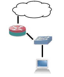
But of course it requires a device at home capable of both GRE and BGP. A Cisco router will do, as will Linux with Quagga and many other industrial routers. But the only device I currently have running 24/7 is my WS-C3560-8PC switch. Although it has an IP Services IOS, is already routing and can do GRE and BGP, it doesn’t do NAT. Easy enough: allow GRE through on the router that does the NAT in the home network. Turns out the old DD-WRT version I have on my current router doesn’t support it. Sure I can replace it but it would cost me a new router and it would not be a challenge.
SwitchRouting2

Solution: give the switch a direct public IP address and do the tunnels from there. After all, the internal IP addresses are encapsulated in GRE for transport so NAT is required for them. Since the switch already has a default route towards the router, set up host routes (a /32) per remote GRE endpoint. However, this still introduces asymmetric routing: the provider subnet is a connected subnet for the switch, so incoming traffic will go through the router and outgoing directly from the switch to the internet without NAT. Of course that will not work.

SwitchRouting3

So yet another problem to work around. This can be solved for a large part using Policy-Based Routing (PBR): on the client VLAN interface, redirect all traffic not meant for a private range towards the router. But again, this has complications: the routing table does not reflect the actual routing being done, more administrative overhead, and all packets originated from the local switch will still follow the default (the 3560 switch does not support PBR for locally generated packets).

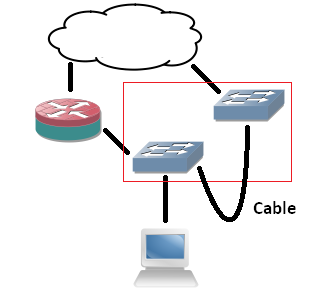
Next idea: it would be nice to have an extra device that can do GRE and BGP directly towards the internet and my switch can route private range packets towards it. But the constraint is no new device. So that brings me to VRFs: split the current 3560 switch in two: one routing table for the internal routing (vrf MAIN), one for the GRE tunnels (vrf BGP). However, to connect the two VRFs on the same physical device I would need to loop a cable from one switchport to another, and I only have 8 ports. The rest would work out fine: point private ranges from a VLAN interface in one VRF to a next-hop VLAN interface over that cable in another VRF. That second VRF can have a default route towards the internet and set up GRE tunnels. The two VRFs would share one subnet.
SwitchRouting4

Since I don’t want to deal with that extra cable, would it be possible to route between VRFs internally? I’ve tried similar actions before, but those required a route-map and a physical incoming interface. I might as well use PBR if I go that way. Internal interfaces for routing between VRFs exist on ASR series, but not my simple 8-port 3560. But what if I replace the cable with tunnel interfaces? Is it possible to put both endpoints in different VRFs? Yes, the 15.0(2) IOS supports it!

SwitchRouting5

The tunnel interfaces have two commands that are useful for this:

  • vrf definition : just like on any other layer 3 interface, it specifies the routing table of the packets in the interface (in the tunnel).
  • tunnel vrf :  specifies the underlying VRF from which the packets will be sent, after GRE encapsulation.

With these two commands, it’s possible to have tunnels in one VRF transporting packets for another VRF. The concept is vaguely similar to MPLS-VPN,  where your intermediate (provider) routers only have one routing table which is used to transport packets towards routers that have the VRF-awareness (provider-edge).

interface Vlan2
ip address 192.168.2.1 255.255.255.0
interface Vlan3
ip address 192.168.3.1 255.255.255.0
interface Tunnel75
vrf forwarding MAIN
ip address 192.168.7.5 255.255.255.252
tunnel source Vlan2
tunnel destination 192.168.3.1
interface Tunnel76
vrf forwarding BGP
ip address 192.168.7.6 255.255.255.252
tunnel source Vlan3
tunnel destination 192.168.2.1

So I configure two tunnel interfaces, both in the main routing table. Source and destination are two IP addresses locally configured on the router.  I chose VLAN interface, loopbacks will likely work as well. Inside the tunnels, one is set to the first VRF, the other to the second. One of the VRFs may be shared with the main (outside tunnels) routing table, but it’s not a requirement. Configure both tunnel interfaces as two sides of a point-to-point connection and they come up. Ping works, and even MTU 1500 works over the tunnels, despite the show interface command showing an MTU of only 1476!

Next, I set up BGP to be VRF-aware. Logically, there are two ‘routers’, one of which is the endpoint for the GRE tunnels, and another one which connects to it behind it for internal routing. Normally if it were two physical routers, I would set up internal BGP between them since I’m already using that protocol. But there’s no difference here: you can make the VRFs speak BGP to each other using one single configuration.

router bgp 65000
address-family ipv4 vrf MAIN
neighbor 192.168.7.6 remote-as 65000
network 192.168.0.0 mask 255.255.248.0
neighbor 192.168.7.6 activate
exit-address-family
address-family ipv4 vrf BGP
bgp router-id 192.168.7.6
neighbor 192.168.7.5 remote-as 65000
neighbor 192.168.7.5 activate
exit-address-family

A few points did surface: you need to specify the neighbors (the IP addresses of the local device in the different VRFs) under the correct address families. You also need to specify a route distinguisher under the VRF as it is required for VRF-aware BGP. And maybe the most ironic: you need a bgp router-id set inside the VRF address-family so it differs from the other VRF (the highest interface IP address by default), otherwise the two ‘BGP peers’ will notice the duplicate router-id and it will not work. But after all of that, BGP comes up and routes are exchanged between the two VRFs! For the GRE tunnels towards the internet, the tunnel vrf command is required in the GRE tunnels so they use the correct routing table for routing over the internet.

So what makes this not production-worthy? The software-switching.

The ASIC can only do a set number of actions in a certain sequence without punting towards the switch CPU. Doing a layer 2 CAM table lookup or a layer 3 RIB lookup is one thing. But receiving a packet, have the RIB pointing it to a GRE tunnel, encapsulate, decapsulate and RIB lookup of another VRF is too much. It follows the expected steps in the code accordingly, the IOS software does not ‘see’ what the point is and does not take shortcuts. GRE headers are actually calculated for each packet traversing the ‘internal tunnel’ link. I’ve done a stress test and the CPU would max out at 100% at… 700 kBps, about 5,6 Mbps. So while this is a very interesting configuration and it gives an ideal situation to learn more, it’s just lab stuff.

So that’s the lesson, as stated in the beginning: how not to do it. Can you route between VRFs internally on a Cisco switch or router (not including ASR series)? Yes. Would you want to do it? No!

And no FabricPath either. This one works without any active protocol involved, and no blocked links. Too good to be true? Of course!

LAN-NoSTP

Take the above example design: three switches connected by port channels. Let’s assume users connect to these switches with desktops.

Using a normal design, spanning tree would be configured (MST, RPVST+, you pick) and one of the three port-channel links would go into blocking. The root switch would be the one connecting to the rest of the network or a WAN uplink, assuming you set bridge priorities right.

Easy enough. And it would work. Any user in a VLAN would be able to reach another user on another switch in the same VLAN. They would always have to pass through the root switch though, either by being connected to it, or because spanning tree blocks the direct link between the non-root switches.

Disabling spanning-tree would make all links active. And a loop would definitely follow. However, wouldn’t it be nice if a switch would not forward a frame received from another switch to other switches? This would require some sort of split horizon, which VMware vSwitches already do: if a frame enters from a pNIC (physical NIC) it will not be sent out another pNIC again, preventing the vSwitch from becoming a transit switch. Turns out this split horizon functionality exists on a Cisco switch: ‘switchport protect’ on the interface, which will prevent any frames from being sent out that came in through another port with the same command.

Configuring it on the port channels on all three switches without disabling spanning tree proves the point: the two non-root switches can’t reach each other anymore because the root switch does not forward frames between the port channels. But disabling spanning tree after it creates a working situation: all switches can reach each other directly! No loops are formed because no switch forwards between the port channels.

Result: a working network with active-active links and optimal bandwidth usage. So what are the caveats? Well…

  • It doesn’t scale: you need a full mesh between switches. Three inter-switch links for three switches, six for four switches, ten for five switches,… After a few extra switches, you’ll run out of ports just for the uplinks.
  • Any link failure breaks the network: if the link between two switches is broken, those two switches will not be able to reach each other anymore. This is why my example uses port-channels: as long as one link is active it will work. But there will not be any failover to a path with better bandwidth.

Again a disclaimer, I don’t recommend it in any production environment. And I’m sure someone will (or already has) ignore(d) this.

Yes, I’m riding the ‘OMG-NSA!’ wave, but it’s proven to be interesting. Eventually one starts pondering about it and even trying some stuff in a lab. Hereby the results: I’ve managed to introduce a backdoor in a Cisco router so I can log in remotely using my own username and non-standard port. Granted, it’s far from perfect: it’s detectable and will be negated if you use RADIUS/TACACS+. But if you’re not paying attention it can go unnoticed for a long time. And a mayor issue for real life implementation: it requires privileged EXEC access to do it in the first place (which is why I’m publishing this: if someone untrusted has privileged EXEC access, you have bigger problems on your hands).

The compromised system
Backdoor-IOS

The router which I tested is a Cisco 2800 series, IOS 15.1(2)GC. Nothing special here. The router is managed by SSH, a local user database and uses an ACL for the management plane.

Backdoor-VTY

The goal

Accidentally getting the password and gaining access is not a backdoor. I want to log in using my own private username and password, use a non-standard port for SSH access, and bypass the ACL for the management plane.

The Setup part 1 – Backdoor configuration

How it’s done: two steps. First, just plainly configure the needed commands.

Backdoor-Config

  • The username is configured.
  • The non-standard high port is configured using a rotary group.
  • The rotary group is added to the VTY (SSH) lines. Just 0 to 4 will do.
  • The ACL for the management plane has an extra entry listing a single source address from which we will connect.

The setup part 2 – Hiding the backdoor

So far it’s still not special. Anyone checking the configuration can find this. But it can be altered using Embedded Event Manager.

Backdoor-EEM

These three EEM applets will filter out the commands and show a clean configuration instead!

  • The “backDOORrun” is the main applet which replaces the standard “show run” by one that doesn’t list the rotary group, the extra ACL entry, the username and the EEM applets themselves. Note that it’s handy to name all objects part of the backdoor in a similar way, e.g. “backDOOR”, so they are matched with a single string.
  • Since the above only affects “show run” two more applets are required for “show access-lists” and “show ip access-lists”. Note that these are only needed if a non-standard port is used, to mask the ACL.

Detectability

Several things do give away that there might be a back door. First of all, port 4362 will respond (SYN,ACK) to a port scan, revealing that something is listening. Second, although the commands are replaced, there’s a distinct ‘extra’ CLI prompt after the commands:

Backdoor-Detection

This only shows if you don’t do any pipe commands yourself and easily mistaken for an accidental extra hit on the ‘enter’ key, but when you’re aware of it, it does stand out.

And last, once you take the running config from the device (through TFTP for example) and open it in a text editor, everything will show as normal. And by knowing the EEM applet names, you can remove them.

If you’re working in a large enterprise with its own AS and public range(s), you’ll probably recognize the following image:

MultiClientDataCenter

On top, the internet with BGP routers, peering with multiple upstream providers and advertising the public range(s), owned by the company. Below that, multiple firewalls or routers (but I do hope firewalls). Those devices either provide internet access to different parts of the company network, or provide internet access to different customers. Whatever the case, they will have a default route pointing towards the BGP routers (a nice place for HSRP/VRRP).

Vice versa, the BGP routers have connectivity to the firewalls in the connected subnet, but they must also have a route for each NAT range towards the firewalls. This is often done using static routes: for each NAT range, a static route is defined on the BGP routers, with a firewall as a next hop. On that firewall, those NAT addresses are used, e.g. if the BGP has a route for 192.0.2.0/30, those four (yes, including broadcast and network) addresses can be used to NAT a server or users behind, even if those aren’t present on any interface in that firewall.

The problem in this setup is that it quickly becomes a great administrative burden, and since all the firewalls have a default route pointing towards the BGP routers, traffic between firewalls travels an extra hop. Setting up static routing for all the NAT ranges on each firewall is even more of a burden, and forgotten routes introduce asymmetric routing, where the return path is through the BGP. And while allocating one large public NAT range to each firewall sounds great in theory, reality is that networks tend to grow beyond their designed capacity and new NAT ranges must be allocated from time to time, as more servers are deployed. Perhaps customers even pay for each public IP they have. Can this be solved with dynamic routing? After all, the NAT ranges aren’t present on any connected subnet.

Yes, it’s possible! First, set up a dynamic routing protocol with all routers in the connected public subnet. Personally, I still prefer OSPF. In this design, the benefit of OSPF is the DR and BDR concept: set these to the BGP routers so they efficiently multicast routing updates to all firewalls. Next, on all firewalls, allow the redistribution of static routes, preferably with an IP prefix filter that allows only subnets in your own public IP range, used for NAT. Finally, if you need a NAT range, you just create a Null route on the firewall that needs it (e.g. 192.0.2.0/30 to Null0), and the route will automatically be redistributed into OSPF towards the BGP routers, who will send updates to all other firewalls. Problem solved!

But what about that Null route? Won’t packets be discarded? No, because this is where a particular logic of NAT comes into play: NAT translations are always done before the next hop is calculated. A packet entering with destination address pointing towards a Null route (e.g. 192.0.2.1) will first be translate to the private IP address, after which the route lookup gives a connected subnet or another route further into the private network. The Null route is never actually used!

A stateful firewall should be considered a mandatory part of any network design. End user systems and the internet simply cannot be trusted, and even on servers there’s always the unexpected open port possibility. Going completely Cisco here for a moment, it’s an ASA, or a Zone-Based Firewall (ZBFW) configuration on an edge router.

But, usually due to budget constraints, it’s not always feasible to go and put firewalls everywhere in the network. While the WAN or internet edge should really have it, internally it can be less of a need. This is usually where access control lists (ACLs) come into play.

ExampleLan

The example LAN above is completely internal. The switches are layer 2 access switches, the router depicted in the middle is a layer 3 switch acting as a default gateway for the VLANs.

Now let’s assume there’s a web server on 10.3.32.2 and a Voice server on 10.3.32.3. You want the following rules applied:

  • From Clients access to the web server by http.
  • From the IP Phones access to the Voice server using SIP protocol.
  • Allow IP Phones to be pinged from the Voice server.
  • Deny everything else.

On an ASA or any other stateful firewall, this would be a rule specified on VLAN 10, a rule for Voice on VLAN 20 and a rule for ICMP echo on VLAN 800. The stateful part would take care of the rest and automatically allow return traffic for existing connections. For TCP, it does so by checking the three-way handshake (SYN, SYN/ACK, ACK) and checking the connection breakdown (FIN and RST flags). For UDP, most stateful firewalls use a pseudo-stateful behaviour: the first UDP packet in a permitted rule will be set in the state table, with a time-out. Return traffic is accepted as long as the time-out isn’t reached. For each outgoing UDP packet part of the same stream, the timer is reset to zero. This is usually sufficient for connectionless communication.

ACLs however simply perform filtering and do not keep track of sessions. To do a ‘deny everything else’, both incoming and outgoing connections will have to be filtered properly with an ACL. A start would be this:

ip access-list extended VLAN10-IN
permit ip any host 10.3.32.2
ip access-list extended VLAN20-IN
permit ip any host 10.3.32.3
ip access-list extended VLAN30-IN
permit ip host 10.3.32.2 10.0.10.0 0.0.0.255
permit ip host 10.3.32.3 10.0.20.0 0.0.0.255

But the above access-list is very general and leaves a lot of security issues. To make it mimic a stateful firewall, add more details:

ip access-list extended VLAN10-IN
permit tcp 10.0.10.0 0.0.0.255 host 10.3.32.2 eq 80
ip access-list extended VLAN20-IN
permit udp 10.0.20.0 0.0.0.255 host 10.3.32.3 eq 5060
permit icmp 10.0.20.0 0.0.0.255 host 10.3.32.3 echo-reply

ip access-list extended VLAN30-IN
permit tcp host 10.3.32.2 eq 80 10.0.10.0 0.0.0.255 established
permit udp host 10.3.32.3 eq 5060 10.0.20.0 0.0.0.255
permit icmp host 10.3.32.3 10.0.20.0 0.0.0.255 echo

A breakdown of the above added parameters:

  • Specifying a subnet with wildcard rather than just ‘any’, even if there’s just one subnet behind that interface, prevents IP spoofing. If just the return traffic is filtered on the subnet, this still allows for initial SYN packets, so SYN flooding from a spoofed IP is possible when ‘any’ is used.
  • Always specify a destination port to prevent scanning of the servers and accidental (or malicious) connection to other services running on that server. Even if the server runs a software firewall: it shares the operating system with the services, who may open ports on this firewall.
  • ICMP: specific definition of echo and echo-reply makes sure the server can ping the IP Phones, but not the other way around.
  • In the return traffic, setting the source port to the service makes sure the server does not initiate connections, or in the case of UDP, starts a flow on a non-standard port. Since it’s not possible to use timers in the ACL based on outgoing connections, this way you can still do some filtering.
  • For TCP, the ‘established’ keyword only allows packets that have the ACK bit set. The initial SYN used for the connection buildup is not allowed – Effectively preventing the server from initiating a connection himself. Instead, he has to listen for connections from the clients, where the ACK bit isn’t checked.

While this does not create a state table on the switch or router, it really narrows down the attack surface. Connections cannot be initiated where you don’t want it, packets must go to and originate from ports you decide. The biggest security problem is that UDP packets or TCP packets with ACK already set can be used to flood the links, but even then only from certain ports. And, compared to a stateful firewall, this configuration is more complex, because with each rule change, you have to completely understand the flow, and also adapt the ACL for the return traffic.

IPv4 anycast design.

Today, not a new protocol or device, but something else: an anycast design. In IPv6, an anycast address is an address that is in use by multiple devices. A packet destined for this address is sent to one of the devices only, either at random, load balanced, or by shortest distance (geographical location or metric). This article will show a design that does that in IPv4. The anycast service used will be DNS, but it can be anything, going from DNS, DHCP, NTP to protocols that use sessions like HTTP, although it does not provide any stateful failover in case a server fails.

AnycastDesign

The above design shows a head quarters (HQ) with two DNS servers, and a branch office with one local DNS server. In a ‘standard’ design, the three DNS servers would have three different IP’s, e.g. 10.0.2.2 and 10.0.2.3 in the HQ, and 10.1.2.2 in the branch office. The users in the HQ would have 10.0.2.2 as primary DNS and 10.0.2.3 as secondary, with perhaps some subnets doing vice versa to balance the load a bit. The branch office users would use the local 10.1.2.2 DNS as primary, and one of the HQ DNS as backup.

Such a design works and has redundancy, but has a few minor setbacks: in case a DNS fails, the users using it as a primary DNS will have to query the primary, which is down, followed by the secondary. This takes time and slows the systems. Also, a sudden failure of the branch office DNS may put a sudden high load on one of the HQ DNS, as most operating systems only have up to two DNS servers configured by default. The design can be enhanced by implementing anycast-like routing. This can be done in two ways: routed anycast and tracked anycast.

The routed anycast design requires that the DNS servers run a routing protocol, which is achieved easiest by using Unix/Linux operating systems. Each server has a loopback configured with an address like 10.10.10.10/32. Routing is enabled on the server and the address is advertised, for example by OSPF. Each server listens on the loopback for DNS requests, and management is done by the physical interface to still differentiate between DNS servers. The 10.10.10.10/32 is advertised by OSPF throughout the company. Even if it’s advertised from multiple locations, the only one used in each router is the one with the lowest metric, and thus the shortest distance.

The tracked anycast design works without the hosts running a routing protocol, but they still need the loopback with the IP address and routing configured. This makes it more accessible for any kind of server, including Windows. The routers are configured to track the state of the DNS servers using ping, or even by DNS requests. These tracking objects are then used to decide when a static route towards the loopback address of the DNS server is left in the routing table or not:

R1(config)#ip route 10.10.10.10 255.255.255.255 10.0.2.2 track 1

The route is then redistributed in the dynamic routing protocol. This design has several advantages:

  • You need just one IP address for the server and it’s a /32, which means it can be an easy to remember number that is equal in the entire company.
  • You no longer need to figure out which server is closest to the subnet, the routing protocols will do that for you.
  • In case two servers are on an equal distance, they will appear as two equal-cost routes in the routing table and load-balancing will automatically occur.
  • A failure of one of the servers is automatically corrected, and no hosts will have unreachable servers configured.
  • Because the management IP differs from the IP used for the service, it allows for better security or easier defined firewall rules.

The biggest drawbacks of the design are the extra configuration (though this is debatable since the anycast IP is easy to use), and convergence of the routing protocol may make the service temporarily unreachable, which means fine tuning of timers is required.

Time to describe the solution to my last blog post.

Let’s see the topology again:

The router does not have any routing protocol configured. It does have all interfaces configured: 10.0.0.1 towards the WAN cloud, 10.0.1.1 towards the PC 2 subnet, and an IP address towards the PC 1 subnet. PC 2 is a Windows computer, static IP 10.0.1.2. PC 1 is a Windows computer set to DHCP client, but there is no DHCP pool configured on the router or any other device. PC 1 hasn’t had any special changes to the software settings or TCP/IP stack.

Under what circumstances will PC 1 and PC 2 be able to ping each other?

Well, note that I speak of Windows computers. This OS does a very specific thing when there’s no DHCP server: it will use an APIPA address. This is an address in the range 169.254.0.0/16. The remaining 16 hostbits are generated from the MAC address. So despite that I not explicitly give the PC1 IP address, you know in which subnet the IP will be. So the router interface towards PC1 needs an IP in the same subnet. Congrats to Pape Diack for working that out!

That’s half of the challenge. But to ping PC1 from another subnet, it’ll need a default route, which it does not have. Unless it somehow assumes the echo request originated from the local subnet.

First solution: a (static) NAT rule on the router, which translates an IP on another subnet to an IP on the local subnet. For PC1, it seems as if the router sends the echo request. Once the router receives the echo reply, it is translated and sent to PC2.

Second solution: proxy-arp. Enabled by default on a Cisco router. If PC1 doesn’t have a gateway, it desperately tries to ARP for PC2’s MAC address. If the router knows how to reach PC2 (possible through the connected subnet), it will reply with his own MAC, and forward the packet once it arrives.

A third, more out-of-the-box thinking solution was using IPv6, as suggested by some. Granted it would work, but not exactly what I was looking for. I better add more detail to my questions the next time.

Thanks for all the answers!

Something else for a change: a challenge for the reader.

Given the following topology:

The router does not have any routing protocol configured. It does have all interfaces configured: 10.0.0.1 towards the WAN cloud, 10.0.1.1 towards the PC 2 subnet, and an IP address towards the PC 1 subnet. PC 2 is a Windows computer, static IP 10.0.1.2.
PC 1 is a Windows computer set to DHCP client, but there is no DHCP pool configured on the router or any other device. PC 1 hasn’t had any special changes to the software settings or TCP/IP stack.

Now the question: under what circumstances will PC 1 and PC 2 be able to ping each other?

To my knowledge, this question has two possible solutions. You have an idea? Please share it in the comments!

Update: the solution.

For this article, I’m reusing an earlier topology:

Example network

Assume that everything inside is a private range, e.g. 10.0.0.0/8, and the edge router performs NAT to the WAN link with a public address. Once everything is subnetted and a routing protocol is set up, the route table of the routers will most likely show a few internal routes (e.g. 10.0.1.0/24, 10.0.2.0/24,…) and a default route pointing towards the edge router, out to the WAN link.

A simple, effective design. But what about a packet destined for, let’s say, 192.168.1.1? It will not match on any interior routes and will be sent along the default route, out over the WAN link, and get dropped at the first ISP hop (well, it should be). Can that behavior be countered? Yes: add a static route on the edge router to a Null interface, which will silently discard packets. The packets disappear into a black hole, hence the name black hole routing.

Routes to 192.168.0.0/16 and 172.16.0.0/12 can easily be added on every router in the example, as these ranges aren’t present locally and shouldn’t be routable on the internet. And 10.0.0.0/8 can also be added everywhere, but only if no route filtering is performed. A packet for subnet 10.0.1.0/24 will be routed to the correct subnet if it exists, because it’s a more specific route in the route table than 10.0.0.0/8. A packet for a subnet that doesn’t exist, e.g. 10.5.1.0/24, will be dropped because it matches the 10.0.0.0/8 Null route, instead of the default route.

If route filtering is performed, things become a bit more complex. It’s usually still possible to add the 10.0.0.0/8 Null route on the edge router, but inside an OSPF totally stubby area, for example, only default routes are injected into the area. Adding the Null route here may result in unreachable subnets.

Personally, I think it’s a good best-practice to black hole some IP ranges instead of letting these packets wander around the network. It keeps things clean. Since it’s also less CPU-intensive on most platforms to perform routing instead of access-lists, it might be used for basic security. Like a black hole to the Facebook IP ranges in your company network if you’re that desperate, for example.

If you know any other interesting uses, please let me know in the comments!

This one’s for you, Chris.

I’ve read countless articles, comments, posts about IPv6 and ‘that there are x IPv6 addresses for every human/square meter/grain of sand… on earth’. Okay, but let’s go hypothetical now, make some assumptions, and try to predict when the IPv6 address pool will be depleted. It’s just for fun, don’t expect any educational value in this article.

I’m going to use powers of ten to keep it somewhat imaginable. The total number of possible combinations with 128 bits is 3.40*10^38.  However, some ranges are unusable for internet routable traffic, and reserved by IETF:

  • FE80::/10 – Link local addresses.
  • FC00::/7 – Unique local packets, somewhat resembling RFC 1918 addresses for IPv4.
  • FF00::/8 – Multicast addresses.
  • 2002::/16 – 6to4 addresses, which are more of a transition mechanism and not really host addresses.

Currently, only the 2000::/3 range is global unicast, but other ranges can be assigned so in the future. The currently assigned range alone gives 4.25*10^37 addresses. For simplicity, I’m going to assume that eventually the entire address range will be used, except 2002::/16 and the entire F000::/4 block. That should cover all current and future reserved assignments. That’s still 3.19*10^38 addresses.

It should be clear by now we will run out of useable MAC addresses much sooner than IPv6 addresses, but let’s leave that out of the equation here. Let’s continue with our 39-digit number. But, even if we assume that in the near future every mobile device has an IP address, and we assume that the number of mobile devices doubles (e.g. one smartphone, one tablet), then we have about 10 billion devices, according to Wikipedia. That’s 10^10, which is nothing next to 10^38. Even multiplying that number by 1000, to cover all servers, point-to-point links, multiple home computers, household devices with an IP (refrigerators, ovens, photo frames, you name it), the total number of cars,… It will ‘only’ count up to 10^13, which doesn’t even scratch the surface of the entire available address pool.

The answer doesn’t lie in counting the number of devices that could possibly have an IP address. But, so far, I have been assuming perfectly filled subnets, no wasted addresses. That’s certainly not going to happen in IPv6: the EUI-64 mechanism for stateless autoconfiguration of IPv6 addresses requires a subnet to have 64 bits. This means most, if not all subnets (except point-to-point links), will have a size of /64 in the future. Highly inefficient for the conservation of addresses. Using the values I assumed earlier, that gives me 1.73*10^19 subnets. So from a 39-digit number, we now have a more realistic 20-digit number.
Let’s try to deplete that by, for example, giving one /56 per house (recommended, but that’s not likely to happen, as described in detail already by network instructor Chris Welsh), and one /48 per company. I haven’t found any definitive numbers, but I think it’s a conservative assumption that there are about 3 people on average sharing one home in the world, with fewer in the Western world (about 2.5 on average) and more in other parts of the world. As far as companies go, I’ve only found one quote saying there were 56 million companies worldwide in 2004, without anything to back it up, but it’s the best I have.

Assuming 60 million companies in 2012 with a /48, and 7.2 billion people, with an average of three per household, for a total of 2.4 billion households with a /56, I can calculate:

  • A /56 is 8 bits, 256 subnets times 2.4 billion makes 614.4 billion.
  • A /48 is 16 bits, 65536 subnets times 60 million makes 3.93*10^12
  • Together, that’s 4.55*10^12 subnets used.

That still doesn’t touch the 10^19 value. However, we now have a number that represents the used number of subnets versus the whole population (and assuming the whole world has access to IPv6 technology and needs it, but hey, we’re making assumptions for the future, and I’m hoping the best for humanity). Dividing our number of used subnets by the population, we get roughly 632 of /64 subnets used per human on this planet.
1.73*10^19 total subnets, divided by 632 subnets per human, gives 27,37*10^15 humans on the planet before the subnets are depleted. That’s 27 million billion. At this point, I was going to take a chart about human population growth, but none of them make predictions past 20 billion.

Conclusion: unless we reach for the stars and spread our IPv6 address space over the entire galaxy (even our solar system wouldn’t do), or finally perfect nanotechnology and decide to give each nanobot his own IPv6 address, we will not run out of IPv6 addresses. Even with large error margins, there are simply too many addresses and too few things to give it to. ISPs, hand out those /56 already!