Tag Archive: Spanning Tree


Disclaimer: the logs are taken from a production network but the values (VLAN ID, names) are randomized.

Recently, I encountered an issue on a Campus LAN while performing routine checks: spanning tree seemed to undergo regular changes.

The LAN in question uses five VLANs and RPVST+, a Cisco-only LAN. At first sight there was no issue:

BPDU-Trace1

On an access switch, one Root port towards the Root bridge, a few Designated ports (note the P2P Edge) where end devices connect, and an Alternative port in blocking with a peer-to-peer neighborship, which means BPDUs are received on this link.

There is a command that allows you to see more detail: ‘show spanning-tree detail’. However, the output from this command is overwhelming so it’s best to apply filters on it. After some experimenting, filtering on the keywords ‘from’,’executing’ and ‘changes’ seems to give the desired output:

BPDU-Trace2

This gives a clear indication of something happening in the LAN: VLAN 302 has had a spanning-tree event less than 2 hours ago. Compared to most other VLANs who did not change for almost a year, this means something changed recently. After checking the interface on which the event happened, I found a port towards a desk which did not have the BPDU Guard enabled, just Root Guard. It was revealed that someone regularly plugged in a switch to have more ports, which talked spanning-tree but with a default priority, not claiming root. As such, Root Guard was not triggered, but the third-party switch did participate in spanning-tree from time to time.

Also, as you notice in the image, VLAN 304 seemed to have had a recent event to, on the Alternative Port. After logging in on the next switch I got the following output:

BPDU-Trace3

Good part: we have a next interface to track. Bad news: it’s a stack port? Since it’s a stack of 3750 series switches, it has stack ports in use, but the switches should act as one logical unit in regards to management and spanning-tree, right? Well, this is true, but each switch still makes the spanning-tree calculation by itself, which means that it can receive a spanning-tree update of another switch in the stack through the stack port.

Okay, but can you still trace this? You would have to be able to look in another switch in the stack… And as it turns out, you can:

BPDU-Trace4

After checking which stack port connects to which switch in the CLI, you can hop to the next one with the ‘session’ command and return to the master switch simply by typing ‘exit’. On the stack member, again doing the ‘show spanning tree detail’ command shows the local port on which the most recent event happened. And again the same thing: no BPDU Guard enabled here.


And no FabricPath either. This one works without any active protocol involved, and no blocked links. Too good to be true? Of course!

LAN-NoSTP

Take the above example design: three switches connected by port channels. Let’s assume users connect to these switches with desktops.

Using a normal design, spanning tree would be configured (MST, RPVST+, you pick) and one of the three port-channel links would go into blocking. The root switch would be the one connecting to the rest of the network or a WAN uplink, assuming you set bridge priorities right.

Easy enough. And it would work. Any user in a VLAN would be able to reach another user on another switch in the same VLAN. They would always have to pass through the root switch though, either by being connected to it, or because spanning tree blocks the direct link between the non-root switches.

Disabling spanning-tree would make all links active. And a loop would definitely follow. However, wouldn’t it be nice if a switch would not forward a frame received from another switch to other switches? This would require some sort of split horizon, which VMware vSwitches already do: if a frame enters from a pNIC (physical NIC) it will not be sent out another pNIC again, preventing the vSwitch from becoming a transit switch. Turns out this split horizon functionality exists on a Cisco switch: ‘switchport protect’ on the interface, which will prevent any frames from being sent out that came in through another port with the same command.

Configuring it on the port channels on all three switches without disabling spanning tree proves the point: the two non-root switches can’t reach each other anymore because the root switch does not forward frames between the port channels. But disabling spanning tree after it creates a working situation: all switches can reach each other directly! No loops are formed because no switch forwards between the port channels.

Result: a working network with active-active links and optimal bandwidth usage. So what are the caveats? Well…

  • It doesn’t scale: you need a full mesh between switches. Three inter-switch links for three switches, six for four switches, ten for five switches,… After a few extra switches, you’ll run out of ports just for the uplinks.
  • Any link failure breaks the network: if the link between two switches is broken, those two switches will not be able to reach each other anymore. This is why my example uses port-channels: as long as one link is active it will work. But there will not be any failover to a path with better bandwidth.

Again a disclaimer, I don’t recommend it in any production environment. And I’m sure someone will (or already has) ignore(d) this.

If you ever managed a Campus LAN, you’ll know what happens with a lot of end users that have access to ethernet cables on desks. The occasional rogue hub, a loop now and then, and if they have access to some more advanced tools, some BPDU’s and a rogue DHCP server. Most of these events are not intended to be malicious (even the BPDU’s and rogue DHCP), but they happen because end users are not aware of the impact of some devices on the network.

But, given a malicious intend, what are the possibilities of attacking a switched Cisco network from a directly attached interface? Operating system for all the upcoming attacks: BackTrack Linux, which has many interesting tools installed.

MAC Flood
The classic attack first: flooding the switch’s CAM table with random source MAC addresses.
Tool: macof
Countermeasure: port-security

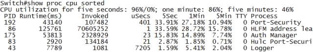
First attacking without port security: as expected, CAM table fills, CPU increases and everything is flooded. Congestion everywhere.

L2Attack-1

Finding this attack without port-security is feasible by checking CPU processes: HLFM address learning doesn’t normally consume that much CPU. Turning of MAC address learning does the same but without CPU impact.

So does turning port-security on solve the problem? It depends. Turning it on and setting it to only block new mac addresses but not shutting down the port actually makes things worse for the CPU:

L2Attack-2

The best solution: port-security with shutdown of the port in case of too many MAC addresses. No flooding, no CPU hogging.

CDP Flood
A Cisco-only attack. Flooding CDP frames with fake neighbors, causing not only CPU spikes, but also clogging the memory with all the neighbor entries. ‘show cdp neighbor’ becomes like showing the route table on a BGP router: endless.
Tool: Yersinia
Countermeasure: disabling CDP on the port or globally.

The attack with CDP turned on (the default) is very effective:

L2Attack-3

Finding the attack is easy, as both CPU and memory will clearly show the CDP process is using up resources. However, without CDP on the port, the attack does nothing. So the best solution: always turn CDP off towards a user-facing port. Even behind an IP Phone, although some functionality will be lost.

Root BPDU inject
A funny one. Inject a BPDU claiming to be root to cause spanning-tree recalculations and creating suboptimal paths in the network.
Tool: Yersinia
Countermeasure: Root Guard.

L2Attack-4

Notice the root ID, which has a nearly identical MAC address to make it difficult to spot the difference, and the aging time of two days, making this an attack that will last while the attacker is no longer connected. Root Guard on the port counters this attack easily though.

BPDU Flood
This attack doesn’t try to change the spanning-tree topology, but rather overload the STP process. Consequence is high CPU and eventually spanning tree inconsistencies.
Tool: Yersinia
Countermeasure: BPDU Guard

L2Attack-5

Spanning-tree should not use that much CPU on a switch. HLFM address learning will increase too due to the random source MAC addresses, and depending on the switch, Hulc LED Process will increase too. This is the process that governs the LED status of all switchports: the more ports the switch, the more this process will consume CPU if flooding attacks are happening.

BPDU Guard stops this effectively by shutting down the port. BPDU Filter not so much: it still needs to look at the BPDU to drop it and not forward it in hardware. BPDU Filter is generally not recommended anyway.

DHCP Discover Flood
Not really a layer 2 attack, but still impacting for the local subnet. Sending a flood of DHCP Discover messages, quickly overloading the DHCP Server(s) for the subnet.
Tool: Yersinia
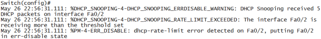
Countermeasure: DHCP Snooping and DHCP Snooping Rate Limit

If DHCP Snooping isn’t enabled on the switch, it behaves like a MAC Flood attack and can be countered accordingly. Simply enabling DHCP Snooping, which is against rogue servers and not against flooding, makes things worse.

L2Attack-6
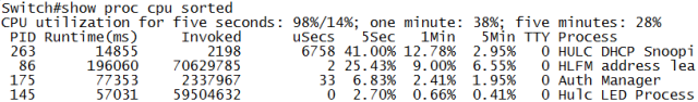
Not only does it make the CPU spike, but it’s one of the few attacks that makes the switch unresponsive in the data plane, meaning not only management is lost, but the switch stops forwarding most frames, with packet loss on all ports. Simple snooping does prevent execution from a virtual machine:

L2Attack-7

But to really protect against this attack, DHCP Snooping rate-limiting helps:

L2Attack-8

OSPF Flood
Sending a flood of OSPF Hello packets over a switch.
Tool: a virtual machine running ospfd (Vyatta, OpenBSD), and a hub between switch and computer with cable loop to cause the flood.
Countermeasure: ACL

For this one I didn’t use any specific tool. I just made my computer send out an OSPF Hello, and made sure the hub between computer and switch was wired so it would flood the frame. Result: spectacular. The switch CPU rises to 100% and management connections, including console, are dropped. Reason is that the OSPF process has higher priority. But now the shocking part: this was done on a layer 3 Cisco switch without OSPF configured, and without an IP address in the attacker VLAN.

Explanation: Cisco switches use something called pak_priority. It means that certain packets on ingress are labeled by the interface driver as priority and to be checked by CPU (Source). This is done to make sure network control packets get to the CPU in case of congestion. It’s the case for RIP, OSPF and EIGRP, but not for BGP packets.

I retried it with EIGRP (although this required a second Cisco device to generate the EIGRP hello) and the result is the same: no EIGRP configuration on the switch, still impact. The data plane does not have any impact: forwarding stays as usual mostly.

Solution? Strange enough, an ACL on each port blocking EIGRP (IP Protocol 88) and OSPF (IP Protocol 89) and allowing everything else seems to work. The ACL is checked in hardware as long as the ‘log’ parameter isn’t present. So for better security, it seems you’re stuck with an ACL on each switchport of a layer 3 switch.

Conclusion
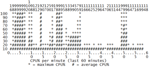
I’m sure most of the readers now conclude that there’s still a security leak somewhere in their network. Just for reference, I’ll include the CPU graph of an hour of testing all these attacks.

L2Attack-9

Loop prevention and limitation.

When dealing with large layer 2 broadcast domains, loop prevention becomes one of your main concerns. Loops cause broadcast storms, and broadcast storms bring down networks.

But loop prevention in a data center is not simple. For one, you’re not in control of all devices capable of forming a loop. You’re not even in control of every device capable of generating spanning tree BPDU’s. And then there are vSwitches, which are switches but don’t use spanning-tree (an in-dept discussion of this can be found on Ivan Pepelnjak’s blog, here and here). To finish it off, Nexus 2000 Fabric EXtenders have BPDU Guard hardcoded, although I’ve been informed this might change.

Despite the above gaps in uniformity for spanning-tree, it’s still considered mandatory to run it on the network. Without it, things would be much worse and a proper spanning-tree design with an appropriate type (MST, RPVST) can prevent most issues. BPDU Guard towards (non-hypervisor) servers is a second rule of thumb.

But BPDU Guard only activates upon receiving a BPDU, and loops don’t always carry BPDU’s. This is where storm-control comes in the picture: it checks the number of broadcast, multicast and unknown unicast frames over a 1 second period. If it reaches a configured threshold, any following offending packets are dropped in that 1 second interval. Optionally, the port can be err-disabled, and snmp traps can be sent. Configuration is as following:

Switch(config-if)#storm-control broadcast level pps 100
Switch(config-if)#storm-control multicast level 2.00
Switch(config-if)#storm-control unicast level bps 1m
Switch(config-if)#storm-control action shutdown
Switch(config-if)#storm-control action trap

This is just a sample config: broadcast, multicast and unknown unicast can be configured separately. The threshold can be expressed in percentage of total bandwidth (2.00), packets per second (pps 100) and bits per second (bps 1m, or 1,000,000). There is no real guideline for good values, because it depends on your network. The more you know which traffic flows through it, the better you can set a good value. It’s not a perfect solution, but it’s a measure of last resort for when a loop does occur. The ‘shutdown’ action should only be configured on the same links where you would want BPDU Guard.

So are inter-switch links safe then? Unfortunately not, due to the architecture of switches that forward in hardware.

DataAndControlPlane

The hardware forwarding uses ASICs that only know how to forward. This is referred to as the data plane. The CPU does not do any forwarding (well, it can, but it shouldn’t), and is referred to as the control plane. It monitors the switch health, processes BPDUs, CDP frames, and optionally for a layer 3 switch, the routing protocols and the routing table (but again, not the actual layer 3 forwarding). If the control plane takes a hit and crashes (bug, exploit, sometimes hardware), the control plane will crash. But chances are the data plane will not. And without control plane to limit it, the data plane will happily start forwarding any frame entering the switch out of every other port, regardless of VLAN, CAM table or layer 3 headers. Even ports configured as layer 3 will start flooding.

You might notice ICMP replies mentioned in the picture. This can be an attack vector on a layer 3 switch: generating many frames with low TTL will cause it to generate ICMP TTL Expired messages. Combined with ping replies and incoming packets for non-existing hosts in connected subnets, which will generate ARP requests, this can burden a switch CPU beyond normal expectations.

When this happens, storm control with SNMP traps is one of your best options to quickly finding and limiting the problem on a large layer 2 domain. Another option in the initial design is using actual routers for layer 3 boundaries if possible: the interfaces are hardcoded layer 3 and will not start flooding when the control plane crashes.

I’m noticing a shift in focus in my articles: from theory to a more practical approach. This one, hopefully, is a mix of both: BPDU Guard and BPDU Filter.

Let’s start with the theory first: for those who don’t know, BPDU Guard is a feature on Cisco switches which causes a switchport to shut down as soon as it receives a spanning-tree frame. BPDU Filter doesn’t shut down the port, but instead filters out the BPDU, as if it was never received on that port. Both features can be configured globally on the switch, or on a per-port basis. Now to the practical side of things:

BPDU Guard
A port with BPDU Guard will still send out BPDU frames itself. This comes in handy, as two access ports with PortFast and BPDU Guard connected to each other in a Campus LAN will detect the BPDUs and shut down the port. This is a good practice, as you don’t always control what end users connect to the network: their own switches, hubs, computers with network cards placed in bridging mode… All of these aren’t a real problem until somehow a second connection is made. Using the command ‘spanning-tree portfast bpduguard default’, each PortFast port will automatically have it configured. You can even configure ‘errdisable recovery cause bpduguard’ and the switch will recover automatically from these incidents, no need for manual intervention.
But… There are downsides. First of all, the port isn’t shut down until an actual BPDU frame is received: since spanning-tree does this every two seconds by default, a broadcast frame can still loop for two seconds before the port is disabled. That might not be impressive, but it’s sometimes enough to briefly send a spike through the network. Also, while this does stop most loops made through IP Phones, I’ve heard people say some IP Phones filter out BPDU frames. And while the errdisable autorecovery saves management overhead, the loop will briefly reappear as long as the problematic cable isn’t removed.

BPDU Filter
BPDU Filter on a port filters out any received BPDU frames, but at the same time, it stops sending BPDUs as well. It effectively stops spanning-tree from operating on that port, so this port will stay enabled no matter what happens to the spanning-tree topology. Very tricky, as it’s always possible someone misplaces a cable (and we’re all human, so that will happen eventually).
Also… While ‘spanning-tree portfast bpdufilter default’ seems to enable it globally on the switch, it works different: it doesn’t send out BPDU frames on PortFast ports, but once a BPDU frame is received, the port loses PortFast status and starts working like a normal switchport, sending out BPDUs again.
Personally, I strongly dislike experimenting with spanning-tree in such a way, but in a rare occasion, it might be the only option. That rare occasion usually involves a Nexus 2000 Fabric Extender: the access ports are hardcoded with BPDU Guard enabled, so the only way to connect a switch to it is if that switch does not send out any BPDUs. A risky setup.

Any comments? Feel free to share the bridging loop horror stories!

Not every layer 2 design is the same. There are a lot of features and techniques you can use in a layer 2 LAN, but it really depends on the purpose of the LAN what is going to be effective and what not. Sometimes, it’s better to leave some features out because of unexpected consequences otherwise.

So far, in my experience, I’ve encountered four distinct types of layer 2 networks in practice.

The typical Campus LAN or office network is a network where mostly end users connect. In it’s most simple form, it’s one VLAN where the computers connect. As it grows, it will usually have a second VLAN for IP Phones, and if even larger, separate VLANs for different kinds of users, a separate VLAN for in-office services (think printers, content displaying media, perhaps security camera’s), and in case of a full-scale wireless architecture, a separate VLAN for Lightweight Access Points (LAPs). Typically, DHCP is going to be used a lot here, and users expect a ‘fast user experience’, which usually translates to low-latency, low- to medium bandwidth usage. Only rarely end users require full gigabit connectivity towards the desktop (although they usually think they do).

The following are typical design characteristics of such a Campus LAN:

  • The typical access ports with optionally an auxiliary VLAN for Voice. Static configuration, perhaps dynamic VLAN assignment through 802.1x or other means if you’re up to the task.
  • Things like ‘switchport nonegotiate’ and ‘no cdp enable’ should be obvious on these access ports. If Cisco IP Phones are used, CDP may be of use though.
  • Interesting security features: DHCP Snooping (switch uplinks trusted), activated on client VLANs, port-security, BPDU Guard. Keep in mind port-security will count for any MAC address on any VLAN, so the IP Phone counts as one. Even setting the limit to 5 MAC addresses is better than not setting it at all, as it will counter any MAC exhaust attack.
  • If you’re worried about having to go and re-enable a switchport every time BPDU Guard or port-security kicks in, you can configure err-disable recovery. If you don’t think that will happen at all, you have too much confidence in mankind.
  • IP Phones require PoE and most models are capped at 100 Mbps, making a gigabit switch redundant if you daisy-chain computers behind the IP Phones. Personally, I like 100 Mbps to desktops in most situations, as applications don’t require more and it’s an easy way to limit one user from pulling too much bandwidth without configuring QoS.
  • ARP Inspection, while certainly a good feature, may rarely not work correctly I’ve noticed. Still, a Campus LAN is the most likely place you’ll see an ARP Spoofing attack.
  • Think dual stack. I’m going to stress my IPv6 RA Guard post once more to counter any IPv6-related attacks on the subnet. Blocking IP protocol 41 (IPv6 over IP) out of the network will counter any automatic tunneling mechanisms client devices may have (and Windows 7 has one configured by default).
  • Taking the above in account, Cisco 2960 and 2960S series are usually perfect for this environment, with 3560v2 and 3750X should layer 3 switches be required.

A Server LAN is a bunch of physical servers connected to switches. A smaller company’s own Server LAN is often just one VLAN for all the servers. If there are internet-faced servers, like web servers or a proxy, they should have a dedicated ‘DMZ‘ VLAN, as these servers are most prone to direct hack attempts. Unlike the Campus LAN, high traffic volumes may occur in this here.

TypicalDesign

  • At least gigabit is needed for a decent server, as multiple users will connect to one server. 100 Mbps is not forbidden, some services barely use bandwidth.
  • DHCP Snooping and ARP Inspection are quite useless here. Servers have static IPs, and getting ARP Inspection working in such an environment requires a lot of static entries, configuration overhead, and difficult troubleshooting.
  • The above mentioned RA Guard for IPv6 does stay valid, because of the different approach of IPv6. Use with care when used in software though.
  • Port-security works, and can map a MAC address to a port. Servers don’t usually move in a physical environment, but in a virtualized environment with vMotion and the like, it’s of not much use.
  • Things like ‘switchport nonegotiate’ and ‘no cdp enable’ should be obvious again.
  • BPDU Guard, even on trunk links to servers, is a good idea. Some might argue that it’s not good to have an important server disconnected from the network because it happens to send out a BPDU frame by mistake, but I personally don’t consider that a network-related problem.
  • Private VLANs can seriously increase security if deployed properly. It’s usually sufficient if the servers can communicate with the gateway. Doesn’t work if the servers need to see each other (a cluster heartbeat for example), and in virtualized environments, as it doesn’t work with VLAN tagging.
  • If the budget allows it and you require QoS and bigger buffers, a Cisco 4948 becomes an interesting option.

A Data Center LAN is like a Server LAN, but heavily consolidated. Virtualization places many servers on one physical uplink. While a large company’s data center will not have a large number of VLANs, a colocation data center can have hundreds of VLANs, and even reach the maximum of 4096 VLANs in extreme cases.

  • I consider gigabit mandatory, and 10 Gbps is becoming the standard these days. After all, several virtual servers share the link, and FCoE further consumes bandwidth.
  • The remaining configuration is like a Server LAN, but because of the shared environment and a lot of trunk links, Private VLANs are not an option. DTP and CDP disabled on the server links, and BPDU Guard are the only usable security features.
  • Again, IPv6 RA Guard, although I would recommend either IPv6 stack disabled, or configured static.
  • QoS features would be recommended.
  • Spanning-tree mode here should be MST. RPVST+ will generate many BPDUs that have to be handled in software.
  • Data Center LAN requires data center switches. At least Cisco 4948, but this environment is the home of chassis switches, Cisco 4500, 6500, and the Nexus family.

The last layer 2 network is a core network. It’s an environment that does not do any filtering or functionality other than forwarding as fast as possible, e.g. a large Campus LAN core, or a provider backbone where BGP transit traffic passes.

  • This is 10 Gbps or faster.
  • As little extra functionality besides forwarding as possible, and if present, done in hardware.
  • Cisco’s 6500 chassis has 10 Gbps blades, and even a new 4-port 40 Gbps blade: WS-X6904-40G-2T. Extreme Networks seems to have a more extended portfolio here, with the BlackDiamond X chassis claiming up to 192 40GbE ports.

This is just my opinion on things, a first combination of theoretical knowledge and field experience. If you don’t agree, let me know in the comments – I’m hoping for a discussion on this one.

I’m going to take a risk here and challenge myself to a discussion that has been active for years among data center network engineers: eliminating Spanning-Tree Protocol from the data center.

To the readers with little data center experience: why would one want to get rid of STP? Well, a data center usually has a lot of layer 2 domains: many VLANs, many servers. That translates to many switches. Those switches require redundant uplinks to the core network, and maybe each other too. Using STP, you can achieve such redundancy, but at the cost of putting links in blocking state. Okay, MST and PVST+ allow you to assign root switches per VLAN or group of VLANs and do some load-balancing across the links, but it can still result in inefficient switching where a frame goes through more switches than it needs to. Port-channels use all links, but they are not perfect and can only be configured between two (logical) devices.

STP Network

If you’re still not convinced, take the above example. The red and blue line are two connections. While the blue connection does take the shortest path, the red one does not. This is because STP puts some links in blocking state to prevent loops. You can change the root bridge, but choosing a root bridge that is not in the center of the network makes things worse.

Outside of the data center, there is not such a need for improved switching: smaller networks like SOHO or medium size companies don’t have large layer 2 topologies so STP is sufficient, and an ISP, while having a large infrastructure, often uses layer 3 protocols for redundancy because the number of hosts doesn’t matter, only routing data does.

There are several technologies being developed to improve switching and most are based on the proposed TRILL standard: TRansparent Interconnect of Lots of Links. Switches use a link-state protocol that can run on layer 2, IS-IS, which does not carry any IPv4 or IPv6 routes in this implementation, but MAC address locations.

TRILL header

Frames are encapsulated with a TRILL-header (which has it’s own hop count to prevent switch loops) and are sent to the switch that is closest to the destination MAC address. If the entire layer 2 topology runs TRILL, that means it will be sent to the switch that is directly connected to the destination MAC address. The TRILL header is then removed to allow normal transportation of frames again. The entire frame is transported as payload in the TRILL header, even the 802.1q VLAN tag is left unchanged. Basically, it is like ‘routing frames’. For broadcasts and multicasts, a multicast tree is calculated to allow the copying of frames without causing loops. Reverse-Path Forwarding (RPF) checks are also included to further reduce potential switching loops. Also, equal-cost multipath is supported, so load-balancing over multiple links within the same VLAN is possible.

While TRILL is a proposed IETF standard, 802.1aq SPF or Shortest Path Bridging is an IEEE standard. It works very similar and also uses IS-IS with multicast trees for broadcasts and unknown unicasts, as well as RPF checks. The mayor difference is in the encapsulation: either 802.1ah MAC-in-MAC or 802.1ad QinQ is used. MAC-in-MAC encapsulates the frame in another ‘frame’ with source and destination MAC addresses of switches, while QinQ manipulates VLAN tags to define an optimal path. The actual workings are quite complex but can be studied on Wikipedia.

Of course, new protocols in the networking world always come as vendor-specific too, and naturally Cisco is part of it. Cisco uses FabricPath, which is a custom TRILL implementation that can already be configured the Nexus 5500 and 7000 series. It also claims that all switches capable of FabricPath today will be able to support TRILL too once it’s an official standard.

Brocade, originally a SAN vendor with lots of products in the data center network market now, has VCS Fabric Technology, which also is a custom TRILL implementation. While some suggest it does not scale that well compared to other products, it does come with some auto-configuration features that make it easy to deploy.

Juniper also has a vendor-specific protocol to move away from STP: QFabric. It’s not TRILL-based, making it less likely to allow multi-vendor support on existing hardware in the future. A QFabric works like one giant managed switch: it’s like a large chassis made up of multiple physical devices, in some aspects like the Nexus 2000 FEX’es, which act as line cards for a parent 5000 or 7000. Multiple QFabric’s can be connected and appear to each other as one switch, allowing it to scale out very well. For an in-dept explanation, EtherealMind has explained it very well.

Which one is best? Future will tell: all these technologies are relatively new (TRILL isn’t even official yet), and not widely deployed yet. It also depends on what infrastructure you have in mind, the budget, and vendor preference.

Port-aggregation: lifting the confusion.

I’m seeing a lot of people discussion port-aggregation on fora lately, and it seems there are a lot of misconceptions about this. In this article, I’m going to review some mechanics of port-aggregation.

First a quick review of port-aggregation: it is the binding of multiple physical links between two devices to one single logical link, for increased bandwidth and redundancy. In Cisco terminology it’s often called a Port Channel or EtherChannel.

Switch to switch port-channel.

Port-aggregation is a layer two thing and is configured on switches, not routers. People have asked me what’s the difference with HRSP/VRRP, as they both provide redundancy. If you need to ask that, it’s best that you start over and learn the OSI model again (yes, small rant, but really…). Since it’s layer two, it has nothing to do with IP’s.

The links have to be of the same speed, duplex mode and media type, but they do not have to be of the same length (that would be impossible in most real-world situations). If one of the links falls back from 1 Gbps to 100 Mbps or from full duplex to half duplex, it is excluded from the channel. This may happen if a copper pair gets damaged, as 1 Gbps uses all four copper pairs in a wire, and 100 Mbps and half duplex use less pairs.

There are three types of port-aggregation: static, LACP or PAgP. PAgP is Cisco proprietary, LACP is not. Both send control frames on each physical link and will try to negotiate a port-channel. This is recommended because if you do a static configuration but configure the wrong port, a loop may occur.
A static channel can be useful if you need to set up port-aggregation to a device that does not support LACP. Usually this is a server with multiple NICs, like a VMWare ESX. The standard vSwitch supports port-aggregation but no LACP.

Server to switch port-channel.

Because the links form one logical channel, it becomes one link for STP. If you have the choice, port-aggregation is always better than two separate links. There is not a single argument that will convince me otherwise. Port-aggregation failover occurs in less than a second, perhaps millisecond range, which STP can’t compete with even when fine tuned. It also makes no sense to have two or more links between two switches and just use one of them.
There is no notable difference in latency between one physical link or a port-channel, so it’s not a factor to consider in any design.

I often see a discussion that ‘the total bandwidth of two links is 400 Mbps because it’s full duplex’. In total, yes, but it’s still just 200 Mbps in one direction. Since it’s not said that a single 100 Mbps link ‘is 200 Mbps because it’s full duplex’, it’s better not to listen to the marketing talk and use the single numbers. A modern network has no hubs – You can assume everything is full duplex, and keeps things simple when calculating bandwidth.

Physical link selection.

The frame still has to travel through one of the physical links. The physical link is chosen based on a hashing algorithm: source and/or destination MAC address, source and/or destination IP address, and on a 6500 chassis source or destination port. This means that a ‘conversation’ always travels over the same physical line: if two computers do a data transfer, they use the same MAC, IP and port during the entire transfer, on both sides. So a single transfer can never take more bandwidth than one single physical link: over an 8 Gbps port-channel or eight 1 Gbps links, the maximum speed of a file transfer still is 1 Gbps. Port-aggregation is designed to be used between multiple hosts.
This also means that the theoretical maximum bandwidth is rarely reached, as one of the links will usually reach 100% before the others do. In case of just a few devices combined with a bad hashing algorithm, throughput may still be low as all transfers go through one physical link.

Conversations going through one link does come with an advantage. Because port-aggregation links can be of a different length, sending frames of the same conversation over different links could cause some jitter, which is bad for things like voice and streaming. A 6500 chassis allows something called ‘adaptive hashing’ which would divide frames more evenly over the links.

Switch Stack

And the last interesting fact about port-aggregation: it’s only possible between two devices, but the definition of ‘device’ can be stretched here: a stack of switches (e.g. Cisco 3750) can act as one logical switch, with one management IP and each switch appearing as another module. E.g. a link on the first switch, port 12 (F1/0/12) and a link on the third switch, port 20 (F3/0/20) can be used together in a port-channel. Another example is port-aggregation starting from two different FEX’es, which appear as a module in a parent Cisco Nexus (see my introduction to the Nexus series for more information). Two 6500 chassis can also be used together as a Virtual Switch System (VSS), which is one logical switch.
The only notable exception with Cisco is the Nexus series, where two Nexus 5000 or 7000 can form a port-channel with a third device, with a management link between them to synchronize everything.

Layer 2 security methods.

Another week has passed and I’ve used it to concentrate on layer 2 security: DHCP Snooping, Dynamic ARP Inspection and IP Source Guard. I had trouble getting the latter two to work until I realised they work together with DHCP Snooping, and static entries you have to define. But it works now, another thing learned, another check box for the Cisco SWITCH exam.

Time to list some common layer 2 security methods. I will briefly discuss each one here. Note that I use example values, and where I use a VLAN, you can also use a VLAN list most of the time. The interface range command works for these commands as well, allowing for faster configuration.

Port security
The easiest one I think: binds a MAC address to a switchport, so only that host can connect to only that switchport. By default, only one MAC address is allowed, but you can set it to more. Recommended in case of IP Phones, or a hypervisor with multiple virtual machines. Commands:

Switch(config-if)#switchport port-security
Switch(config-if)#switchport port-security mac-address sticky
Switch(config-if)#switchport port-security violation restrict

The second command uses the ‘sticky’ keyword. This means the first MAC address to be detected will be used and added to the running-config. Saves you the time of typing a lot of MAC addresses. The violation mode is restrict here, which drops frames from other MAC addresses and logs an SNMP trap. ‘protected’ would do the same without SNMP trap, and ‘shutdown’ would shutdown the port so nothing can be received on it anymore.

DHCP Snooping
Prevents a rogue DHCP server from handing out IP addresses in the network. The point is not that IP addresses are handed out, but the DHCP server determines the default router, allowing it to influence routes. Personally, I don’t think it’s an often used attack, but it also builds a DHCP binding table on the switch that can be used to prevent other attacks. Configuration:

Switch(config)#ip dhcp snooping
Switch(config)#ip dhcp snooping vlan 1

This activates it for VLAN 1. Of course, the link going to the right DHCP server should be trusted:

Switch(config-if)#ip dhcp snooping trust

IP Source Guard
This function makes sure that a frame sent by a host really came from that host. It does so by comparing the source IP with the source switchport. For the source IP, it either needs the DHCP snooping database (which you can see with the ‘show ip dhcp snooping’), or statically defined entries. An example of a statically defined entry:

Switch(config)#ip source binding 0010.72ab.07f5 vlan 1 192.168.0.5 interface FastEthernet0/3

To enable it, the command must be done on the interface(s):

Switch(config-if)#ip verify source

You can also add the keyword ‘port-security’ after this to check the right MAC address too, but port-security has to be enabled.

Dynamic ARP Inspection
DAI makes sure no false ARP replies or gratuitous ARPs (GARP) are sent. Like IP Source Guard, it uses either the DHCP snooping database or static entries. The static entries are defined with an arp access-list:

Switch(config)#arp access-list ExampleARPlist
Switch(config-acl)#permit ip host 192.168.0.5 mac host 0010.72ab.07f5

To apply it on a VLAN:

Switch(config)#ip arp inspection vlan 1
Switch(config)#ip arp inspection filter ExampleARPlist vlan 1

Private VLANs
I’m mentioning them here because it adds to the security. Very useful in environments where you want hosts to communicate with the gateway, but not each other. For a configuration example, see one of my first blog posts.

802.1x
This makes sure only hosts with the right credentials can connect. A client device must have support for this, but every modern operating system has this. A client device provides a username and password (usually to be filled in somewhere in the network interface options). This password is then checked against a database, usually by RADIUS. If the right credentials are provided, the client device gains access to the network. Activating it requires several commands, as authentication has to be set up. I’m not going to explain how to set up the RADIUS server here.

Switch(config)#aaa new-model
Switch(config)#radius-server host 192.168.1.1
Switch(config)#aaa authentication dot1x default group radius
Switch(config)#dot1x system-auth-control

Switch(config-if)#dot1x port-control auto

Disable Dynamic Trunking Protocol
To prevent a device from forming a trunk link with a switch, and thus gain access to all VLANs, always disable DTP on end-node links:

Switch(config-if)#switchport nonegotiate

BPDU Guard
To prevent any of the end-nodes from taking over as a spanning-tree root bridge, it’s best to configure BPDU Guard. Since these switchports can also be configured with portfast for faster convergence, you can enable BPDU Guard by default too:

Switch(config)#spanning-tree portfast bpduguard default

Switch(config-if)#spanning-tree bpduguard enable

Alternatively, you can configure ‘bpdufilter’ instead of ‘bpduguard’. The difference is that with the first command BPDUs will be filtered, whereas the second command will disable the port.

Preventing double tagging
And finally, this method has no real commands but is just a best-practice: always try to set the native VLAN on trunks to an unused VLAN, and choose another VLAN than VLAN 1 for management. This makes it harder to find the management VLAN, and prevents VLAN hopping attacks. VLAN hopping is done when a frame is sent with two 802.1q tags, of which the first one belongs to a native VLAN. At a trunk link, the first tag will be stripped off the frame, and when received on the next switch, the second VLAN tag will be used. This way, the frame ‘hops’ between VLANs, making attacks possible that are hard to trace.

Broadcast storms: causes and consequences.

A network engineer (to be) who has seen a broadcast storm in a network firsthand can tell you that it’s one of the worst things that can happen to your network. There are different types of broadcast storms, different causes, and depending on the devices in use, different effects can occur.

Most common cause is when an end user connects a hub to the company network, and by some mistake this device is then connected back onto another switchport in the company network. The loop created will catch all frames passing by, keeping them in the loop. But it does not have to be a hub: the same can be done by connecting both Ethernet ports of an IP Phone to a switch, or by connecting a computer to a port while still connected to the company wireless, and the network cards have been set into bridging mode. This is not so far-fetched, laptop network cards are sometimes put into bridging mode by end users to provide wireless to multiple laptops in a hotel room, for example.

Enough blaming the end users. Sometimes beginning network engineers somehow think it’s a good idea to disable spanning-tree. Most luminous of them do it on a production environment. But another problem is when connecting an access port of one VLAN to an access port of another VLAN, or having a native VLAN mismatch on a trunk link. Since this involves two VLANs, if a loop is accidently created, spanning-tree protocol can’t always correctly figure out how to stop it, and the loop persists.

The consequences can differ. If it’s a user VLAN on your access switches, and the problem is noticed fast, it may just be unicast frames stuck in a loop, affecting only the switch CPU, generating MAC address flaps (because the frame source address pops up on different switchports constantly), and eventually congesting bandwidth. But sooner or later, one of the devices is going to send a broadcast frame. And since a typical Windows computer asks for ARP information every two minutes, it’s going to be sooner. That’s when the fun starts. A broadcast frame is going to be flooded out of every switchport. So is a unicast with unknown destination, but a broadcast frame will be processed in software by every end device, whereas a unicast not destinated for the device will be dropped by the network card. That broadcast takes CPU cycles, and a storm of them (read: millions) can take a computer down in seconds.

The situation is worse in a virtualized environment: a network card on a hypervisor platform works in promiscuous mode, accepting every frame and passing it on to the software stack. This means any broadcast storm, even unknown unicasts, will make the hypervisor suffer 100% CPU load. Broadcasts are passed on to the guest operating systems by default, so the problem only gets magnified.

And last: if the switches reach 100% CPU, which does take a while but can happen if the loop goes unnoticed, chain reactions may follow. Frames may be discarded on different VLANs, BPDUs may not be forwarded, causing even more spanning-tree instabilities, and so on. In the core of your network, a broadcast storm has the potential of bringing down the entire network up to the access layers.

So when dealing with Layer 2 networks, take your time to secure them. Configure BPDU Guard, Loop Guard, disable unused ports to prevent accidental loops, check for native VLAN consistency, monitor network device CPU usage, and keep layer 2 domain small if possible. Large layer 2 domains certainly have advantages, but it’s unwise to stretch them across WAN links for example.

But what when one does happen? Well, there are no commands to stop them as far as I know, so the only thing that helps, is finding the loop fast, and unplugging the devices causing it.

Have you every witnessed (or caused) a broadcast storm? Share your stories in the comments.