Tag Archive: Wifi


QoS part VII: wireless.

Back to the definition of QoS in part I: a mechanism to determine which packet to process next in case of unavailable resources. While unavailable resources usually referred to bandwidth, and ASIC throughput in case of some 6500 line cards, for wireless the limiting factor is transmit opportunities.

Contention Window
Wireless is a half-duplex medium, and as such uses CSMA/CA to check if the wireless frequency is occupied by another wireless node before transmitting a frame. Before sending, the wireless node waits a random period of time. The random period of time is between a fixed back off time and a Contention Window (CW). The time is expressed in ‘slots’, and I’m unable to find any documentation that explain what a slot is. It might be a microsecond, but nothing I found confirms this.

The CW has a minimum value and a maximum value. Before a frame is transmitted, the wireless device will wait a fixed back off time plus a random extra time between zero and the minimum contention window, CWmin. If transmit fails (due to a collision in the wireless half-duplex medium), the process will be retried, again with fixed back off time, but with a larger contention window. If transmission fails again, the process will continue until a set number of tries is reached, after which the frame is dropped. The CW will increase every time until a fixed maximum value is reached: CWmax.

WifiQoS-1

Using low CW values means the packet has low latency, but the chance for collisions increases. A higher CW means a higher average latency, and more possible jitter. CW is a number between 1 and 10. That number is not the number of slots, but it’s part of the formula 2^x-1 = slots. A CW of 3 is 7 slots (2^3-1). A CW of 5 is 31 (2^5-1). For example, frames transmitted with a fixed back off time of 5, a CWmin of 4 and a CWmax of 6 will have on average 12 slots of latency when there’s little traffic (5 + 15/2), and if traffic increases, it goes up and can reach 20 slots latency on average (5+31/2).

Traffic classes
This is where the wireless QoS comes into play: the 802.11e standard allows traffic to be split up into classes that each receive different back off times and CWmin and CWmax values. Contrary to switches and routers, it’s a fixed number of classes, with a fixed name. Ironically, voice is given a CoS value of 6 in the wireless world, not 5. The table gives these values:

WifiQoS-2

This table is directly from the Wikipedia page about 802.11e.

Configuration
The configuration on an Aironet is the same as other Cisco devices as far as classification goes, but the difference is in the output queueing with the contention window. Let’s assume we want to classify a RTP voice stream, UDP port 16384, as CoS 6, and everything else as CoS 0:

AP1142N(config)#ip access-list extended AL4-RTP
AP1142N(config-ext-nacl)#permit udp any any eq 16384
AP1142N(config-ext-nacl)#exit
AP1142N(config)#class-map CM-RTP
AP1142N(config-cmap)#match access-group name AL4-RTP
AP1142N(config-cmap)#exit
AP1142N(config)#policy-map PM-Wifi
AP1142N(config-pmap)#class CM-RTP
AP1142N(config-pmap-c)#set cos 6
AP1142N(config-pmap-c)#exit
AP1142N(config-pmap)#class class-default
AP1142N(config-pmap-c)#set cos 0
AP1142N(config-pmap-c)#exit
AP1142N(config-pmap)#exit
AP1142N(config)#interface Dot11Radio 0.10
AP1142N(config-subif)#service-policy output PM-Wifi

Note that the policy is applied on a subinterface in the output direction: it’s for sending only, and on a per-SSID basis. This is not the case for the actual CW configuration: it’s on the main interface because it’s how the antenna will work.

AP1142N(config)#interface Dot11Radio 0
AP1142N(config-if)#dot11 qos class best-effort local
AP1142N(config-if-qosclass)#fixed-slot 5
AP1142N(config-if-qosclass)#cw-min 3
AP1142N(config-if-qosclass)#cw-max 5
AP1142N(config-if-qosclass)#exit
AP1142N(config-if)#dot11 qos class voice local
AP1142N(config-if-qosclass)#fixed-slot 1
AP1142N(config-if-qosclass)#cw-min 1
AP1142N(config-if-qosclass)#cw-max 3

The classes have fixed names which can’t be changed. CoS 0 maps to the best-effort class, CoS 6 maps to the voice class. By giving lower values to the voice frames, these will, on average, experience less latency and be transmitted faster. They are also more likely to be transmitted because the back off timer will expire faster. Result: even when the wireless network is dealing with a lot of traffic, voice frames will be transmitted faster and with less jitter.

This article doesn’t cover anything needed in day-to-day networking, but I’ve found this useful to give me insights into the workings of wireless. Also, although the article is named ‘Wireless signal modulation’, the mechanics are the same for every analog medium that has to transport digital signals, such as coax and DSL.

How does digital data go through the air? For starting, it needs a carrier signal: a certain electromagnetic wavelength that provides a base clock and carries the data through the air.

CarrierWave

This is a basic carrier wave that does not contain any data. Transporting digital data, bits, over this can be done in different forms:

Frequency Modulation
This form of modulation changes the frequency of the carrier wave: a ‘0’ bit for normal frequency, a ‘1’ bit for higher frequency.

FrequencyModulation
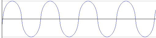
So the above would be read as ‘0100’. I’m making an exaggeration here in the picture, displaying the ‘1’ as double the frequency as a ‘0’. In reality, it would be just slightly higher.

Amplitude Modulation
Changing the amplitude, or intensity of the wave, is another form of modulation. A higher energy wave means a ‘1’, so the same ‘0100’ from FM would look like this in AM:

AmplitudeModulation

Phase Modulation
This one might be a bit more difficult to see: each ‘up and down’ from the carrier wave is one phase. By changing the starting point of each phase, it’s possible to encode information in it. Again the same ‘0100’ where a ‘1’ means the phase will start halfway:

PhaseModulation

Quadrature Amplitude Modulation
QAM is what modern wireless uses. It’s a combination of the above. In most cases it’s AM and PM or AM and FM combined. The use of combining these modulations is that you can encode twice as much per phase.

QuadratureAmplitudeModulation

The above is ‘00110000’ in QAM, using AM and PM combined. But so far, it’s only one bit per modulation per phase. This can be extended. For example, by using 4 different wave intensities (amplitudes), two bits at a time can be transmitted (00, 01, 10 and 11 are four combinations). Multiple frequency changes allow for more than one bit as well, and by starting the phase not only halfway, but also at 1/4, or even 1/8, more bits can be carried. For example, QAM-16 looks like this:

QAM16-Stream

Each phase here can carry four bits (a total of 16 combinations) at a time. Each phase here is called a ‘symbol’ because there’s a unique waveform or symbol for each pattern. The first two bits in this example are the amplitude part: ’00’ for a normal wave, ’11’ for the second wave, which have a four times higher amplitude, and so on. The remaining two bits are from the phase: ’00’ for a normal phase, ’01’ for a phase that starts at 1/4.

Modulator and antenna sensitivity
Now, unlike what most people think, a higher quality (and higher priced) access point doesn’t transmit more signal, thus having a better coverage. In most cases it’s just as much as a cheap access point, because of government regulations. In Europe, an access point is not allowed to send out more than 100 mW at 2.4 Ghz. The reason higher quality access points work better is in their ability to more precisely generate the carrier wave, and the higher sensitivity to pick up the signal correctly from other devices.

In reality, the carrier wave isn’t perfect. There are always small deviations from the ideal wave. Within certain thresholds, the receiving station can still correct this. A higher quality access point generates waves that deviate less from the ideal wave, thus making it easier for other devices (laptops,…) to pick up the signal correctly, even over greater distances. In return, these access points have more sensitive antenna’s that can pick up weakened signals that a lower quality access point could not have.

Frequency
The base frequency for most standards is fixed. 802.11b & 802.11g use the 2.4 Ghz band, 802.11a and the new 802.11ac standard use the 5.0 Ghz band. Only exception is 802.11n, the current mainstream standard, which can use both bands. This does have some consequences: while 2.4 Ghz did a better job penetrating through most materials compared to the 5.0 Ghz band, it does work at the same frequency as a microwave oven. Turning a microwave oven on near a laptop does decrease throughput (note: a microwave leaks a small amount of radiation, see this link for study results). My own tests gave a 40% decrease in throughput on 2.4 Ghz wireless at 3 meters distance of a microwave oven.

On the other hand, switching to 5.0 Ghz does often result in a little less coverage (except outside of course). I had about 10% less throughput in my own house when switching to the 5.0 Ghz band. But 10% is not that much and it also depends on what other nearby access points already use. But it does make a point: if you’re using the 2.4 Ghz band right now, there’s no real guarantee that your brand new 802.11ac router in a year or two will give the same coverage everywhere in the house.

I know I said in my last blog post that I’d be discussing the OSI layer, but I left my documentation at work and I received a nice package in the mail yesterday: an AIR-LAP1142N-EK9.

1142NIt’s a fully capable 802.11n access point, both 2.4 Ghz and 5 Ghz capable, powered by either an external adapter or PoE. It came without adapter and with Lightweight Access Point (LAP) IOS on board, hence I got it rather cheap. Of course, I don’t have a Wireless LAN Controller (WLC) lying around that can configure a LAP. So I had to convert the IOS image to one of a standalone AP.

That proved difficult at first. The 1142N does have a console port, but after booting up it starts searching for a WLC and gets stuck in a loop: DHCP, searching WLC? releasing IP, DHCP, searching WLC,… So console access was not possible. On top of that, it didn’t reply to ARP requests, except for those originating from the subnet gateway (I suspect this is a security feature).

But, just as with Cisco switches, the 1142N LAP has a mode button, and if you hold it while it powers up, it will not load in any configuration or IOS but instead will fallback to IP 10.0.0.1/24 and query for a TFTP server, requesting a file named ‘c1140-k9w7-tar.default’ It does this by sending out broadcasts. I’ve set up a TFTP server in the same subnet (e.g. 10.0.0.10/24) and indeed it reacted… But nothing happened: still ARP information missing. So, after creating a static ARP entry of the 1142N on the TFTP server, TFTP started working! The 1142N retrieved the IOS, and after rebooting it showed as ‘LAP-1142N-EK9 running AP-1142N-E-K9 IOS’. It requested an IP address by DHCP again, after which it was accessible by telnet. Default username and password: Cisco/Cisco. After gaining telnet access, most things were similar to any other Cisco device: SSH key generation, line vty, interfaces,… After configuring it, it didn’t disappoint: throughput was around 95 Mbps, while it was connected on a 100 Mbps PoE switch, and at 20 meters and three walls, still 80 Mbps!

There’s an increase in articles on the web lately about the ‘new wifi standard’, 802.11ac. It seems Asus has released a router supporting the standard, together with a PCI and a USB Wireless NIC supporting it. But while Asus tries to market it as the first in its kind, the actual winner here is Buffalo, who launched the first 802.11ac capable router in May. Meanwhile, other vendors like Aruba and Netgear have started giving some basic information about the standard on their page.

But, they all seem to forget one thing: the 802.11ac standard isn’t finalized yet. The standard will be finalized around 2013 it seems. In that regards, it’s the 802.11n story all over again, where ‘pre-802.11n’ and ‘802.11n-draft’ routers flooded the market long before the actual standard. That means there’s no guarantee pre-draft access points will work with the final standard. Granted, there’s a high chance they will, but it’s still not 100% sure.

So what’s the all the fuss about? Bandwidth of course, as it is the most significant improvement over the existing standards. Let’s check the theoretical specifications:

Frequency
802.11ac is 5 Ghz only. Where 802.11b and g used 2.4 Ghz, and 802.11n could use both 2.4 Ghz and 5 Ghz, it’s only 5 Ghz for the ac-standard, just like 802.11a. This should mean less interference from household equipment (a microwave uses the 2.4 Ghz frequency), but the 5 Ghz frequency cannot penetrate concrete walls as well as 2.4 Ghz. If you immediately think of this as a downside, remember that less penetration also means less noise from neighboring networks.

Channel width
Up until the 802.11n standard, channels were 20 Mhz wide. The 802.11n standard changed that and also allowed for 40 Mhz channels on the 5 Ghz frequency. 802.11ac abandons 20 and 40 Mhz altogether and uses 80 Mhz channels by default, with 160 Mhz as an option. Needless to say, broader channels mean more throughput, as modulation techniques can be improved: the wider the channel, the less error-prone it is.

Spatial streams
Quite a complex technology, but simply explained it allows for different antennas to communicate over the same frequency, each one in its own spatial stream. 802.11n allowed four spatial streams, 802.11ac allows for eight, which means up to eight antennas can be used.

Actual bandwidth gain
So yes, what is the actual bandwidth gain? Well, the increased channel width and improved technology by itself allow for 433 Mbps throughput in one stream, on a standard 80 Mhz channel. 160 Mhz doubles this to 867 Mbps per stream. Note that I’m talking about streams, and 802.11ac allows up to eight streams, so this translates to a theoretical maximum bandwidth of 6.93 Gbps. Impressive for a wireless technology! However, in real world scenarios receivers will most likely have three antennas, so three streams, and handheld devices like cell phones just one. If, just like with 802.11n, only the standard channel width is used, thats 1.3 Gbps for most devices, and 433 Mbps for handheld devices. Since it’s wireless, half duplex, a realistic value would be half of this, meaning around 500 Mbps actual throughput for computers with a decent wireless NIC, and about 200 Mbps for a handheld device. Still, great values, and you can expect a full 4.3 gigabyte DVD to be copied over in raw format in under 90 seconds at 500 Mbps.

What are your thoughts? Do you see any practical applications with this? I certainly do!

A little bit of everything.

Yes, a bit of everything, that’s what it has been lately. First, I’m upgrading my home lab switches with more recent IOS versions. The 3560 on my desk can now run EIGRP for IPv6. My 2970 gigabit switch will follow tomorrow, with a K9 IOS this time to make it accessible via SSH.

Second is that I’ve been fine tuning my knowledge of layer 2 security features, using my 3560 desk switch and a 3750 test switch as subjects. RA Guard works great, and so does DHCP Snooping. DHCP Snooping has revealed a third functionality to me, next to countering rogue DHCP servers and preventing DHCP flooding: it also detects when a MAC address that sends an INFORM cannot be present on that port according to the mac address-table. It will generate a ‘%DHCP_SNOOPING-5-DHCP_SNOOPING_MATCH_MAC_FAIL’ message and drop the frame. Seems to be a functionality related to ARP Inspection.
And ARP Inspection, on the other hand, requires some planning of your DHCP servers: if multiple are present and they all reply at the same time, the DHCP Snooping feature, on which ARP Inspection relies, sometimes picks the wrong packet to add to it’s binding table. The client device selects another packet of the ones it received to configure itself, and thus ARP Inspection thinks there’s spoofing going on. I’m still figuring out how to effectively counter that.

Third is that I’ve ordered the CCIE Routing and Switching Certification Guide, 4th Edition hardcover, so I have a lot of reading to be done soon. I have to admit that I don’t like to read ebooks on a big screen so far, and I’m reluctant to buy a reader.
Yesterday I also tried a MPLS lab for the first time, with BGP-MP in GNS3. It did take me several hours but I managed to get it running. Not bad for never having done anything MPLS related before. Still, it’s a huge topic and I’ll need to learn a lot more about that.

And last, I tested an Aruba Remote Access Point (RAP). I’ve already tested Instant Access Points. The RAP works different: once booted, it needs an internet connection. When connecting a computer (it has LAN interfaces, just like a consumer-grade router), it redirects to a setup page, where you have to enter the public IP address of a Wireless LAN Controller (WLC). It then tries to negotiate a tunnel through NAT-T over UDP port 4500 to that WLC. It works by encapsulating IPsec in a UDP header, bypassing any NAT devices that are incapable of keeping the NAT state of IPsec.
The RAP tries to authenticate itself at the WLC using his MAC address. After whitelisting it and configuring a wireless profile (which contains the list of SSIDs to send out), I had to reboot the RAP. I ended up rebooting it several times, thinking it didn’t work, but eventually it turned out my cable had broken due to all the times I plugged it in and out again. The RAP booted fine and started sending out the correct SSIDs. Initially, the wireless connection didn’t hand out an IP to me, but after five minutes, everything suddenly got an IP and started working as if there had never been a problem. Not sure why this happened, although I suspect my NAT router of dropping some of the UDP packets (which wouldn’t be the first time).

A little bit of everything indeed.

Testing two Aruba IAP.

The title may sound familiar. This time, I was able to test two Aruba Instant Access Points. Both come with a virtual controller, and when they are plugged in on the same network, the fun begins. But first, a rough sketch of my lab lay-out:

LayOut

The two Aruba’s are connected on different switches, 15 meters apart. Connected to the same switch as the first is a Linksys 802.11b/g AP running DD-WRT, connected to the other switch is a Motorola Docsis 3.0 802.11n. But once all devices are plugged in, I only see three wireless networks, not four: the Aruba’s detect each other and automatically use the same settings. That’s right: everything is the same: SSIDs, encryption,…

How did this happen? Well, the Aruba’s send out probing frames on the local subnet, which search for other Aruba devices. Since these are layer 2 frames without IP address, it’s somewhat similar to CDP or LLDP. Once an IAP sees such a probe frames of another IAP, ARP information is requested for layer 3 communication, and the Aruba’s start communication with UDP port 8211 (both source and destination) over IP. They use the PAPI protocol, or Aruba AP control protocol. Settings are transferred from one AP to the other. Since one was configured before and the other one was not, the unconfigured one inherited the settings of the other. I’m not sure what other parameters are used to decide which settings are valid and which not.

PAPI

Since both Aruba’s are now connected, I can log in to the management page on instant.arubanetworks.com, which takes me to the ‘master’ IAP. It shows the same information as before: how many clients are connected, which networks are giving interference,… Only, this time, it show the connected clients per IAP, and interference is also shown per IAP, allowing for some geographical tracking of the clients and access points:

Locating

Compared to the lay-out, the stronger signal indicates the access point is closer. The Linksys is detected on both Aruba’s, the Motorola is just out of reach of one, and has a weaker signal in general.

Because of the copied settings, layer 2 roaming is flawless. The only time frame errors start to occur is when closer than 1 meter from an IAP, which is normal because too close causes echo in the frame transmissions.

Well, nothing really new this time to learn, but some really interesting things about wireless, and the closest I can get to a WLC (Wireless LAN Controller) in my home lab.

Testing an Aruba IAP.

Once again, I was presented the opportunity to test out a device my work borrowed me. This time: an Aruba IAP 105.

IAP105

It’s an Instant Access Point, which comes with a built-in virtual controller. Aruba usually makes Lightweight Access Points (LAPs) which need a central WLC or Wireless LAN Controller to function. Since this one contains the controller function inside the device, I can go experimenting. Yes, it’s like a consumer-grade access point now, with a web GUI to configure it, but compared to the average consumer-grade AP, this one comes with more functionality.

First the standards: it supports 802.11a/b/g/n, with n in both 2.4 Ghz and 5 Ghz frequencies. It also supports 802.3af PoE, or an external power supply, and has support for 802.1q trunking. So as far as compatibility goes, this device supports it all.

After applying PoE to it, it boots up. Since it’s an IEEE compliant power device, and I have a Cisco ILP powered IP Phone on the same switch, this gives a nice comparison:

ShowPowerInline

This shows the IAP as a Class 3 power device, and the IP Phone as Cisco proprietary. The IP Phone gets a slight advantage here as it can tell by CDP how much it needs, thus drawing less power budget. I did not detect any CDP or LLDP support for the Aruba IAP by the way.

Back to the IAP: after booting up and receiving an IP through DHCP, it sends out a default network. After connecting to it, I’m automatically redirected to the login page (Windows 7 even shows an event message ‘Please open your browser’). After entering the default login and password I’m asked in which country I am, likely to comply with local radio regulations.

The main page in the web GUI show some graphs, indicating signal strength, throughput, and number of users connected. Clicking around, I discover noise levels, transmission errors, even individual reports for each client device, as well as a mobility trail, to check the roaming patterns between multiple access points. As I only have one, there’s no useful information there.

The noise levels do indicate a problem:

NoiseProblem

Reason: there are several other access points nearby, one of which is on the same channel 6 as the Aruba. After setting the channel static to 11 (it was automatically searching first), the problem did go away.

Apart from that, there’s also an IDS tab that showed more details about other access points in the area: how far away they are, channel, 802.11 mode, connected clients,… Strangely enough, my own AP is the only one marked as ‘rogue’. Since it’s also the only AP to be in the physically same network as the Aruba, I assume it has some mechanism of finding out unauthorized APs. Maybe it has found the AP’s MAC address in the same VLAN?

As far as configuring SSIDs goes, it have plenty of options too: multiple VLANs are supported, each with it’s own security features. There’s support for WPA, WPA2, WPA2 through RADIUS, MAC filtering, also optionally through RADIUS, 802.1x WEP, and open network. There’s also the option to do a redirect to a login webpage, either hosted on the IAP itself or on an external web server. Network access can be done either through NAT on the IAP, direct access to the uplink (access port) or VLAN tagged to a trunk link. The last one is very useful and what it’s usually all about: by mapping different SSIDs to different VLANs, and connecting the Aruba IAP with a trunk link, one can give access to different subnets through one AP. The authentication (usually by RADIUS) then checks whether access to a certain VLAN is allowed or not. On top of that, it’s possible to set up a per-SSID access list to deny access to certain resources or networks from the IAP.

I did ran into a few unexpected problems. First was that my 802.11n capable laptop could not pick up any 5 Ghz signal, only 802.11n on 2.4 Ghz worked. Second was setting up the trunk link, which didn’t work at first until I realized I was acting too quickly and ‘spanning-tree portfast’ is not the same as ‘spanning-tree portfast trunk’, making the trunk link go through STP states.

And in case you were wondering: yes, the signal strenght of the device is great. I had no stability issues, connecting went fast and reliable.

Wireless best practices.

A while ago, I mentioned I would make a separate blog post for recurring situations in wireless environments. So here I will go over some common points to help improve wireless connections.

The standards
Wireless currently uses the standards 802.11a, 802.11b, 802.11g and 802.11n. The first to standards are rarely used but often present in wireless access points (which I will call WAPs for the rest of the article) for backwards compatibility.
Wireless-g is still the most deployed standard these days, with a theoretical throughput of 54 Mbps, with a range of 40 meters. Note the word ‘theoretical’: in practice, it’s about half of each value, about 25 Mbps and 20 meters indoors. Outdoors, with no obstacles, you can get past 20 meters.
Wireless-n is the newest standard, 150 Mbps throughput and 70 meters range indoors. In practice, it’s certainly not 70 meters, and it seems to stop at the same 20 meters as the g-standard, but within those 20 meters the signal is remarkably better. That’s just my personal experience. Throughput is also halved, but 75 Mbps peaks can be reached which allow for the streaming of HD video.

Collision domain and channels
Wireless is a half-duplex medium, which means only one host on a channel can transmit a frame at the same time. It uses the CDMA/CA algorithm to detect and avoid frame collisions. So the more devices are communicating wireless with one WAP, the slower the speed will be. One laptop copying files may reach 25 Mbps on a wireless-g connection, but two laptops copying a lot of data likely get about 11 Mbps each (25 divided by two, minus some increased collisions).
For this, a WAP can be set to a different channel. There are 11-13 channels, depending on the country you’re in. Most WAPs use channel 11 or channel 6 by default. If your neighbours use a WAP and haven’t changed this, you can change the channel you’re using to something else so there is less interference. Preferably choose a channel at 3 steps higher or lower: in most environments, channels 1,3 and 9 are less used and therefore have less interference.

Interference
A lot of objects can cause interference. First are humans. The human body consists of +50% water, which absorbs radio waves. One person is not such a problem, but when deploying wireless in a room filled with people, expect a weakened signal. Another important cause are large electrical objects like refrigerators, washing machines and the like. They contain a thick layer of metal which blocks the signal. Though not often the case, some objects may form a Faraday cage, like microwave ovens (which are electrical on top of that, too) and aluminium window frames. The latter one can effectively block out +80% of the signal. Also, since the winter will start soon, a christmas tree can block signals because it contains electrical cables with lights in a spiral. Yes, I’ve had people complaining to me about poor signal strength, only to find out it started after setting up the tree.
Thick concrete walls can be problematic too, which is unfortunate because this is sometimes the reason people choose wireless instead of cables in the first place. In my personal experience, wireless-n seems to be somewhat better with concrete compared to wireless-g, but it’s not a large difference. Wooden furniture, walls, ceilings seem to be no problem at all.

Echo
If wireless devices are placed too close to each other, echos may occur, and communication becomes slow. This is usually when there’s less than 1 meter between the devices. I’ve seen it happen, but frankly I’ve always wondered why one would use wireless it there’s just one meter of cable needed to solve the problem.

Orientation
Exactly above the antenna of a WAP, signal strength is very poor. So if your laptop is on the first floor and your WAP is exactly below it, it may not connect at all. Most WAPs have an external antenna that you can orientate freely: orientate it so that from the antenna’s perspective, the wireless device is sideways. If you can orientate the antenna on the wireless device as well, do the same.
Wireless-n WAPs often have three antennas, and people usually set them like a fan in three directions (vendors even advertise them like that). This is not necessary, just put them in the orientation which is best for ‘sideways’ communication. The multiple antennas are not for a broader range, but for improved frame receiving: if the frame is not received properly on one antenna, it may be received correctly on another, decreasing the need for retransmissions. They’re also used for multiple individual streams for better throughput.

Security
Leaving a wireless network unsecured these days is one of the most stupid things a network engineer can do. Anybody within range can connect and wreak havoc within the network. MAC address filtering is an option in most WAPs, but that alone is not enough. It’s easy to capture a MAC source address and spoof it.
If you think WEP encryption will be good, try searching for WEP cracking on YouTube and think again. Plenty of tutorials out there. The best option is using WPA2 or WPA-AES for home deployments. When configuring WPA2, try to choose a difficult key, with some randomisation.
Some people suggest turning off SSID broadcast, but this is not always a good idea. Turning off SSID broadcast on the WAP will keep the network invisible to any new device doing a site survey, but the wireless devices already connected to it will start sending out probes when they can’t find the wireless network. So: disabling SSID broadcast, using your laptop on it, then powering up your laptop in a public place away from home will make your laptop send out probes containing the information about your wireless network. So choose carefully, and personally, I wouldn’t do it.
And last: of course never leave the SSID name default, it will allow for easy guessing the WAP vendor, and in turn exploit vulnerabilities or try default passwords (which you should also change).

Multiple WAPs
If the building where you’re installing wireless is large enough, you may need multiple WAPs. In this case you can either use a central controller, or manage them all one by one. I’m not going to talk about the controller-based version, as this is beyond what most home users will need. For multiple standalone WAPs in a home environment, the best thing to do is to keep them all in the same subnet (so use access points, not routers!), use the same SSID (network name) and encryption, but use different channels. This will allow smooth roaming between WAPs when moving mobile wireless devices around the house.

Network card settings
There’s little to change on most wireless network card driver settings. In case of problems, check the following settings:

  • Mode: can be mixed, b-only, g-only, … Check if it’s compatible with your WAP. Mixed is usually okay.
  • Power saving mode: present on some laptop cards. Some models use this too aggressively, causing signal strength problems. Disabling it may help.
  • Roaming aggressivity: when ‘low’ it tries to stay connected as long as possible before searching for a new WAP. Usually ‘low’ is the best choice, except when in areas with lots of WAPs, where ‘high’ will make it choose the closest WAP faster.

Also note that there’s no general standard to express signal strength on laptops and mobile devices. If laptop A has 4 out of 5 bars signal strength, and laptop B has 2 out of 4 bars signal strength, that does not necessarily mean laptop A has a better signal at the moment. Some network cards are more sensitive, and some vendors use another type of scale (e.g. logarithmic versus linear).

If you have anything to add, please let me know in the comments!