Tag Archive: Routing


This article further continues on earlier experiments. While using internal tunnels gave a logically ‘simple’ point-to-point network seen from a layer 3 point of view, it came with the drawback of complex header calculations, resulting in CPU hogging on devices capable of hardware switching. Using some route-maps to choose VRFs for flows proved interesting, but only in particular use cases. It didn’t make the troubleshooting any easier.

There is a better method for dealing with inter-VRF routing on a local device, but it requires a very different logic. Up until now, my articles described how to be able to select a next-hop inside another VRF. Route leaking using BGP, however, leverages a features of BGP that has been described in my blog before: the import and export of routing information in different VRFs.

How does it work? Well, since the BGP process can’t differentiate between VRFs based on names, but instead uses route-targets to uniquely identify routing tables, it’s the route target that matters. Usually, for MPLS-VPN, these numbers differ per VRF. This time, use the same number for two VRFs:

VRF-RouteLeaking1This will tell BGP later on to use the same routing table for both VRFs. Now if you configure BGP…

VRF-RouteLeaking2

… There’s still a separate configuration per VRF. How does the exchange happen? Well: for all routes that are known inside the BGP process. This means any routes from any BGP peer in one of the VRFs are automatically learned in both VRFs. But for static and connected routes, and routes from other routing protocols, you can do a controlled redistribution using route-maps or prefix lists. This way only the routes that need to be known in the other VRF are added.

VRF-RouteLeaking3

The routing table with automatically show routes pointing to different VRFs. On top of that, the forwarding does not require any headers to be added or removed to the packets, so it can be put directly into CEF, allowing for hardware forwarding. And for completeness: the BGP neighborships here are just for illustration of what happens, but no neighborship is required for this to function. BGP just needs to run on the device as a process.

Of course, this is just a simple setup. More complexity can always be added, as you can even use route-maps to set the route targets for some routes.

This article is not really written with knowledge usable for a production network in mind. It’s more of an “I have not failed. I’ve just found 10,000 ways that won’t work.” kind of article.

I’m currently in a mailing group with fellow network engineers who are setting up GRE tunnels to each others home networks over the public internet. Over those networks we speak (external) BGP towards each other and each engineer announces his own private address range. With around 10 engineers so far and a partial mesh of tunnels, it gives a useful topology to troubleshoot and experiment with. Just like the real internet, you don’t know what happens day-to-day, neighborships may go down or suddenly new ones are added, and other next-hops may become more interesting for some routes suddenly.

SwitchRouting1

But of course it requires a device at home capable of both GRE and BGP. A Cisco router will do, as will Linux with Quagga and many other industrial routers. But the only device I currently have running 24/7 is my WS-C3560-8PC switch. Although it has an IP Services IOS, is already routing and can do GRE and BGP, it doesn’t do NAT. Easy enough: allow GRE through on the router that does the NAT in the home network. Turns out the old DD-WRT version I have on my current router doesn’t support it. Sure I can replace it but it would cost me a new router and it would not be a challenge.
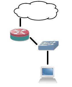
SwitchRouting2

Solution: give the switch a direct public IP address and do the tunnels from there. After all, the internal IP addresses are encapsulated in GRE for transport so NAT is required for them. Since the switch already has a default route towards the router, set up host routes (a /32) per remote GRE endpoint. However, this still introduces asymmetric routing: the provider subnet is a connected subnet for the switch, so incoming traffic will go through the router and outgoing directly from the switch to the internet without NAT. Of course that will not work.

SwitchRouting3

So yet another problem to work around. This can be solved for a large part using Policy-Based Routing (PBR): on the client VLAN interface, redirect all traffic not meant for a private range towards the router. But again, this has complications: the routing table does not reflect the actual routing being done, more administrative overhead, and all packets originated from the local switch will still follow the default (the 3560 switch does not support PBR for locally generated packets).

Next idea: it would be nice to have an extra device that can do GRE and BGP directly towards the internet and my switch can route private range packets towards it. But the constraint is no new device. So that brings me to VRFs: split the current 3560 switch in two: one routing table for the internal routing (vrf MAIN), one for the GRE tunnels (vrf BGP). However, to connect the two VRFs on the same physical device I would need to loop a cable from one switchport to another, and I only have 8 ports. The rest would work out fine: point private ranges from a VLAN interface in one VRF to a next-hop VLAN interface over that cable in another VRF. That second VRF can have a default route towards the internet and set up GRE tunnels. The two VRFs would share one subnet.
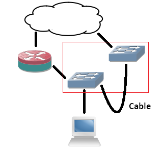
SwitchRouting4

Since I don’t want to deal with that extra cable, would it be possible to route between VRFs internally? I’ve tried similar actions before, but those required a route-map and a physical incoming interface. I might as well use PBR if I go that way. Internal interfaces for routing between VRFs exist on ASR series, but not my simple 8-port 3560. But what if I replace the cable with tunnel interfaces? Is it possible to put both endpoints in different VRFs? Yes, the 15.0(2) IOS supports it!

SwitchRouting5

The tunnel interfaces have two commands that are useful for this:

  • vrf definition : just like on any other layer 3 interface, it specifies the routing table of the packets in the interface (in the tunnel).
  • tunnel vrf :  specifies the underlying VRF from which the packets will be sent, after GRE encapsulation.

With these two commands, it’s possible to have tunnels in one VRF transporting packets for another VRF. The concept is vaguely similar to MPLS-VPN,  where your intermediate (provider) routers only have one routing table which is used to transport packets towards routers that have the VRF-awareness (provider-edge).

interface Vlan2
ip address 192.168.2.1 255.255.255.0
interface Vlan3
ip address 192.168.3.1 255.255.255.0
interface Tunnel75
vrf forwarding MAIN
ip address 192.168.7.5 255.255.255.252
tunnel source Vlan2
tunnel destination 192.168.3.1
interface Tunnel76
vrf forwarding BGP
ip address 192.168.7.6 255.255.255.252
tunnel source Vlan3
tunnel destination 192.168.2.1

So I configure two tunnel interfaces, both in the main routing table. Source and destination are two IP addresses locally configured on the router.  I chose VLAN interface, loopbacks will likely work as well. Inside the tunnels, one is set to the first VRF, the other to the second. One of the VRFs may be shared with the main (outside tunnels) routing table, but it’s not a requirement. Configure both tunnel interfaces as two sides of a point-to-point connection and they come up. Ping works, and even MTU 1500 works over the tunnels, despite the show interface command showing an MTU of only 1476!

Next, I set up BGP to be VRF-aware. Logically, there are two ‘routers’, one of which is the endpoint for the GRE tunnels, and another one which connects to it behind it for internal routing. Normally if it were two physical routers, I would set up internal BGP between them since I’m already using that protocol. But there’s no difference here: you can make the VRFs speak BGP to each other using one single configuration.

router bgp 65000
address-family ipv4 vrf MAIN
neighbor 192.168.7.6 remote-as 65000
network 192.168.0.0 mask 255.255.248.0
neighbor 192.168.7.6 activate
exit-address-family
address-family ipv4 vrf BGP
bgp router-id 192.168.7.6
neighbor 192.168.7.5 remote-as 65000
neighbor 192.168.7.5 activate
exit-address-family

A few points did surface: you need to specify the neighbors (the IP addresses of the local device in the different VRFs) under the correct address families. You also need to specify a route distinguisher under the VRF as it is required for VRF-aware BGP. And maybe the most ironic: you need a bgp router-id set inside the VRF address-family so it differs from the other VRF (the highest interface IP address by default), otherwise the two ‘BGP peers’ will notice the duplicate router-id and it will not work. But after all of that, BGP comes up and routes are exchanged between the two VRFs! For the GRE tunnels towards the internet, the tunnel vrf command is required in the GRE tunnels so they use the correct routing table for routing over the internet.

So what makes this not production-worthy? The software-switching.

The ASIC can only do a set number of actions in a certain sequence without punting towards the switch CPU. Doing a layer 2 CAM table lookup or a layer 3 RIB lookup is one thing. But receiving a packet, have the RIB pointing it to a GRE tunnel, encapsulate, decapsulate and RIB lookup of another VRF is too much. It follows the expected steps in the code accordingly, the IOS software does not ‘see’ what the point is and does not take shortcuts. GRE headers are actually calculated for each packet traversing the ‘internal tunnel’ link. I’ve done a stress test and the CPU would max out at 100% at… 700 kBps, about 5,6 Mbps. So while this is a very interesting configuration and it gives an ideal situation to learn more, it’s just lab stuff.

So that’s the lesson, as stated in the beginning: how not to do it. Can you route between VRFs internally on a Cisco switch or router (not including ASR series)? Yes. Would you want to do it? No!

Just a simple article about something I recently did in my home network. I wanted to prepare the network for a Squid proxy, and design it in such a way that the client devices did not require proxy settings. Having trouble placing it inline, I decided I could use WCCP. However, that requires separate VLANs.

This did pose a problem: my home router did not support any kind of routing and multiple networks beyond a simple hide NAT (PAT) behind the public IP address. Even static routes weren’t possible.

And again my fanless 3560-8PC helped me out. The 3560 can do layer 3 so you can configure it with the proper VLANs and use it as the default gateway on all VLANs. Then you add another VLAN towards the router and point a default route towards that router.

That solves half of the problem: packets get to the router and out to the internet. However, the router does not have a return route for the VLANs. But it does not need that: you can use Proxy ARP. As the router will use a /24 subnet, you can subnet all VLANs inside that /24, e.g. a few /26 and a /30 for the VLAN towards the router, as my home network will not grow beyond a dozen devices in total. Now the router will send an ARP request for each inside IP address, after which the layer 3 switch answers on behalf of the client device. The router will forward all data to the layer 3 switch, who knows all devices in the connected subnets.

ProxyARP

And problem solved. From the point of view of the router, there’s one device (MAC address, the layer 3 switch) in the entire subnet that uses a bunch of IP addresses.

IS-IS part II: areas and backbone.

Given the basics covered in part I, IS-IS configuration isn’t that hard. It already clearly shows some differences with OSPF, but it’s when using multiple areas that there is a clear distinction in logic.

OSPF-Areas

First a small recap of OSPF areas: you have a backbone area, area 0, to which all other areas must connect. A router can be in multiple areas, an interface can be in only one area for a given OSPF process. Routes between areas are known by default, but setting an area to stub can change this to just a default route.

ISIS-Areas

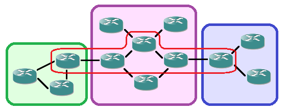
IS-IS is different: as you may have guessed by the ‘net’ command of part I, a router can only be part of one area. Area borders are between routers. An area is made up of routers with level 1 neighborships. A router with a level 2 neighborship towards another router is considered a backbone router. Since level 2 neighborships can be between routers in different areas (the second part of ‘net’ command can differ), these routers connect areas.

The moment a router has a level 2 neighborship and becomes a backbone router, it will automatically propagate a default route towards its level 1 neighbors. This gets flooded throughout the area. To reach another area, packets will be sent automatically towards the nearest backbone router. The Backbone router has a second topology table for level 2 that lists information of all subnets in all areas (which requires more memory). The packet will then be transported over the backbone to the appropriate area. For this reason, the backbone must be continuous: otherwise there would be multiple islands of routers propagating default routes.

From that point of view, the level 2 backbone becomes an overlay on top of the areas that connects everything: an extra ‘level’, likely the reason for the terminology. While this design works and is very scalable it may introduce suboptimal routing. Inter-area traffic will go to the nearest backbone router, but there may be other backbone routers in the area that can route the packets to the destination in a better way. For example, in the above image, the bottom router in the purple middle area may decide to follow the default route to the left backbone router for a packet destined for the right blue area.

Configuration is still straightforward:

Router(config)#interface GigabitEthernet0/1
Router(config-int)#ip address 10.0.2.5 255.255.255.252
Router(config-int)#ip router isis
Router(config-int)#isis circuit-type level-1
Router(config-int)#exit
Router(config)#interface GigabitEthernet0/2
Router(config-int)#ip address 10.0.3.1 255.255.255.252
Router(config-int)#ip router isis
Router(config-int)#isis circuit-type level-2-only
Router(config-int)#exit
Router(config)#interface GigabitEthernet0/3
Router(config-int)#ip address 10.0.2.9 255.255.255.252
Router(config-int)#ip router isis
Router(config-int)#
Router(config-int)#exit
Router(config)#router isis
Router(config-router)#log-adjacency-changes
Router(config-router)#net 49.0001.0000.0000.0008.00

This example configures a router for a level 1 neighborship on Gi0/1 (inside the area), a level 2 neighborship on Gi0/2 (between areas) and a level 1 & 2 neighborship on Gi0/3 (inside the area, but still backbone). Note the missing ‘is-type’ command in the routing process, which makes the router default to both a level 1 and level 2 router. A router in another area has a different area number in the net command:

Router(config)#interface GigabitEthernet0/2
Router(config-int)#ip address 10.0.3.2 255.255.255.252
Router(config-int)#ip router isis
Router(config-int)#isis circuit-type level-2-only
Router(config-int)#exit
Router(config)#router isis
Router(config-router)#log-adjacency-changes
Router(config-router)#net 49.0002.0000.0000.0009.00

Note that an IS-IS router is not required to have a level 1 neighborship. It is possible to have a ‘pure’ backbone router with only level 2 neighborships, which makes the router only use one topology table again, just like a level 1-only router.

The topology tables for both levels can be checked with show isis topology l1 and show isis topology l2. Same for the database, just replace the word ‘topology’ with ‘database’. The show clns is-neighbors and show isis neighbors commands both show all IS-IS neighbors and the level of the neighborship.

IS-IS, or Intermediate System to Intermediate System. Just like OSPF, it’s a link-state routing protocol. This article took me quite a bit of research, and things were confusing for me at first because I kept looking at it from an OSPF point of view. Now that I’ve cleared that up for myself, I’ll do my best to explain it here for people knowing OSPF but not IS-IS (which, I assume, will be the majority of readers here).

First some explanation about why one would want to use IS-IS in the first place. After all, both are link-state routing protocols and OSPF is much more familiar to most. However, there are a few key differences in design of the protocols. But the most important reason to choose IS-IS over OSPF is scalability. IS-IS scales to larger topologies compared to OSPF using the same resources. A general recommendation for the number of OSPF routers in an area is between 70 and 100 maximum, while IS-IS will do 150 routers in an area (of course, the number of uplinks, routes and type of routers will influence this number). The difference in multi-area design can also make IS-IS more suitable for some topologies (which I will explain in part II later on).

This part will focus on a single area and basic configuration. It is useful to know some historical facts which explain the difference in commands compared to OSPF.

  • Since IS-IS wasn’t designed with IP in mind but CLNS, it works directly on layer 2 with no IP headers. It uses flexible TLV (Type-Length-Value) fields in the PDUs it exchanges which makes it suitable for carrying routing information of just about any protocol. This is why it’s also used for IPv6 and even TRILL and FabricPath (which is actually nothing more than exchanging the location of MAC addresses by routing protocol).
  • IS-IS has a concept of areas but refers to it as ‘levels’. On a Cisco router the IS-IS routing protocol will try to form neighborships for both level 1 and level 2 by default. When using just one area, it’s best to configure the routing protocol to form neighborship of level 1 only (again, multi-area will be covered in part II).
  • A Network Entitity Title (NET) is used to identify a router. It is made up of four parts: the first byte is an Authority and Format Identifier (AFI),  next two bytes that define the area, followed by six bytes that act as a unique identifier (much like an OSPF router-id) and one byte for n-selector (NSEL). This NSEL is always set to zero for IS-IS for IP (non-zero values are used for actual data transport over CLNS, which likely isn’t used anywhere anymore). The AFI must be officially registered but 49 can be used for internal addressing.
  • As a consequence, the first six bytes (AFI and area ID) have to be the same for all IS-IS routers in an area, and the following six bytes have to be unique for each IS-IS router in an area.
  • For the unique ID part, several methods exist: you can use the system base MAC address, map an IP address to it, or simply start counting from 1 and up.

ISIS-NET

Given all the above, the basic IS-IS routing process can be configured as following:

Router(config)#router isis
Router(config-router)#log-adjacency-changes
Router(config-router)#is-type level-1
Router(config-router)#net 49.0001.0000.0000.0017.00

Unlike the other routing protocols, logging of adjacencies is not on by default on a Cisco router.

Now that the process is configured, interfaces must be added to it. That’s right, interfaces, no ‘network’ command to define subnets. This can be done in two ways:

  • Configuring an IP address on an interface, followed by the ‘ip router isis’ command will make the interface participate.
  • Configuring an IP address on an interface and defining that interface as passive in the router process will make IS-IS announce the subnet on the attached interface but not form any neighborships on it. The ‘ip router isis’ command is not required.

Router(config)#interface GigabitEthernet0/1
Router(config-int)#ip address 10.0.2.1 255.255.255.252
Router(config-int)#ip router isis
Router(config-int)#exit
Router(config)#interface Loopback0
Router(config-int)#ip address 10.0.10.14 255.255.255.255
Router(config-int)#exit
Router(config)#router isis
Router(config-router)#passive-interface Loopback0

And that’s it. Configure this on two adjacent routers and an IS-IS neighborship will form. You can check this using ‘show clns neighbors’ and ‘show isis neighbors’.

ISIS-Show

In upcoming parts, I’ll explain multi-area design and configuration and fine tuning of the default parameters. And for those interested, I’ve uploaded a capture of the IS-IS neighborship forming on Cloudshark.

Advantages of MPLS: an example.

While MPLS is already explained on this blog, I often still get questions regarding the advantages over normal routing. A clear example I’ve also already discussed, but besides VRF awareness and routing of overlapping IP ranges, there’s also the advantage of reduced resources required (and thus scalability).

WANEdgeDesign

Given the above design: two routers connecting towards ISPs using eBGP sessions. These in turn connect to two enterprise routers, and those two enterprise routers connect towards two backend routers closer to (or in) the network core. All routers run a dynamic routing protocol (e.g. OSPF) and see each other and their loopbacks. However, the two middle routers in the design don’t have the resources to run a full BGP table so the WAN edge routers have iBGP sessions with the backend routers near the network core.

If you configure this as described and don’t add any additional configuration, this design will not work. The iBGP sessions will come up and exchange routes, but those routes will list the WAN edge router as the next hop. Since this next hop is not on a directly connected subnet to the backend routers, the received routes will not be installed in the routing table. The enterprise routers would not have any idea what to do with the packets anyway.

Update January 17th, 2014: the real reason a route will not be installed in the routing table is the iBGP synchronisation feature, which requires the IGP to have learned the BGP routes through redistribution before using the route. Still, synchronisation can be turned off and the two enterprise routers would drop the packets they receive.

There are a few workarounds to make this work:

  • Just propagating a default route of course, but since the WAN edge routers are not directly connected to each other and do not have an iBGP session, this makes the eBGP sessions useless. Some flows will go through one router, some through the other. This is not related to the best AS path, but to the internal (OSPF) routing.
  • Tunneling over the middle enterprise routers, e.g. GRE tunnels from the WAN edge routers towards the backend routers. Will work but requires multiple tunnels with little scalability and more complex troubleshooting.
  • Replacing the middle enterprise routers by switches so it becomes layer 2 and the WAN edge and backend routers have a directly connected subnet. Again this will work but requires design changes and introduces an extra level of troubleshooting (spanning tree).

So what if MPLS is added to the mix? By adding MPLS to these 6 routers (‘mpls ip’ on the interfaces and you’re set), LDP sessions will form… After which the backend routers will install all BGP routes in their routing tables!

The reason? LDP will advertise a label for each prefix in the internal network (check with ‘show mpls ldp bindings’) and a label will be learned for the interfaces (loopback) of the WAN edge routers… After which the backend routers know they just have to send the packets towards the enterprise routers with the corresponding MPLS label.

And the enterprise routers? They have MPLS enabled on all interfaces and no longer use the routing table or FIB (Forwarding Information Base) for forwarding, but the LFIB (Label Forwarding Information Base). Since all packets received from the backend routers have a label which corresponds to the loopback of one of the WAN edge routers, they will forward the packet based on the label.

Result: the middle enterprise routers do not need to learn any external routes. This design is scalable and flexible, just adding a new router and configuring OSPF and MPLS will make it work. Since a full BGP table these days is well over 450,000 routes, the enterprise routers do not need to check a huge routing table for each packet which decreases resource usage (memory, CPU) and decreases latency and jitter.

Setting up a routing protocol neighborship isn’t hard. In fact, it’s so easy I’ve made them by accident! How? There were already two OSPF neighbors in a subnet and I was configuring a third router for OSPF with yet another fourth router. But because the third router had an interface in that same subnet and I used the command ‘network 0.0.0.0 255.255.255.255 area 0’ the neighborships came up. This serves as an example that securing a neighborship is not only to avoid malicious intent, but also to minimize human error.

Session authentication
The most straightforward way to secure a neighborship is adding a password to the session. However, this is not as perfect as it should be: it doesn’t encrypt the session so everyone can still read it, and the hash used is usually done in md5, which can easily be broken at the time of writing. Nevertheless, a quick overview of the password protection for EIGRP, OSPF and BGP:

Router(config)#key chain KEY-EIGRP
Router(config-keychain)#key 1
Router(config-keychain-key)#key string
Router(config-keychain-key)#exit
Router(config-keychain)#exit
Router(config)#interface Fa0/0
Router(config-if)#ip authentication mode eigrp 65000 md5
Router(config-if)#ip authentication key-chain eigrp 65000 KEY-EIGRP
Router(config-if)#exit

Router(config)#interface Fa0/1
Router(config-if)#ip ospf message-digest-key 1 md5
Router(config-if)#exit
Router(config)#router ospf 1
Router(config-router)#area 0 authentication message-digest
Router(config-router)#exit

Router(config)#router bgp 65000
Router(config-router)#neighbor 10.10.10.10 remote-as 65000
Router(config-router)#neighbor 10.10.10.10 password

Note a few differences. EIGRP uses a key chain. The positive side about this is that multiple keys can be used, each with his own lifetime. The downside: administrative overhead and unless the keys change every 10 minutes it’s not of much use. I doubt anyone uses this in a production network.

BGP does the configuration for a neighbor (or a peer-group of multiple peers at the same time for scalability). Although there’s no mention of hashing, it still uses md5. It works with eBGP as well but you’ll need to agree on this with the service provider.

OSPF sets the authentication key on the interface and can activate authentication on the interface, but here it’s shown in the routing process, as it’s likely you’ll want it on all interfaces. It would have been even better if it was possible to configure the key under the routing process, saving some commands and possible misconfigurations on the interfaces. OSPF authentication commands can be confusing, as Jeremy points out. However:

OSPFv3 authentication using IPsec
The new OSPF version allows for more. Now before you decide that you’re not using this because you don’t run IPv6, let it be clear that OSPFv3 can be used for IPv4 as well. OSPFv3 does run on top of IPv6, but only link-local addresses. This means that you need IPv6 enabled on the interfaces, but you don’t need IPv6 routing and there’s no need to think about an IPv6 addressing scheme.

Router(config)#router ospfv3 1
Router(config-router)#address-family ipv4 unicast
Router(config-router-af)#area 0 authentication ipsec spi 256 sha1 8a3fe4a551b81dc24f6148b03e865b803fec49f7
Router(config-router-af)#exit
Router(config-router)#exit
Router(config)#interface Fa0/0
Router(config-if)#ipv6 enable
Router(config-if)#ospfv3 1 area 0 ipv4
Router(config-if)#ospfv3 bfd

This new OSPF version shows two advantages: you can configure authentication per area instead of per interface, and you can use SHA1 for hashing. The key has to be a 40-digit hex string, it will not accept anything else. A non-hex character or 39 or 41 digits gives a confusing ‘command not recognized’ error. The SPI vaue needs to be the same on both sides, just like the key of course. The final command is to show optional BFD support.

EIGRP static neighbors
For EIGRP you can define the neighbors on the router locally, instead of discovering them using multicast. This way, the router will not allow any neighborships from untrusted routers.

Router(config)#router eigrp 65000
Router(config-router)#network 10.0.0.0 0.0.0.255
Router(config-router)#neighbor 10.0.0.2 Fa0/0
Router(config-router)#exit

Static neighbor definition is one command, but there is a consequence: EIGRP will stop multicasting hello packets on he interface where the static neighbor is. This is expected behavior, but easily forgotten when setting it up. Also, the routing process still needs the ‘network’ command to include that interface, or nothing will happen.

BGP Secure TTL
Small yet useful: checking TTL for eBGP packets. By default an eBGP session uses a TTL of 1. By issuing the ‘neighbor ebgp-multihop ‘ you can change this value. The problem is that an attacker can send SYN packets towards a BGP router with a spoofed source of a BGP peer. This will force the BGP router to respond to the session request (SYN) with a half-open session (SYN-ACK). Many half-open sessions can overwelm the BGP process and bring it down entirely.

TTL-Security

Secure TTL solves this by changing the way TTL is checked: instead of setting it to the hop count where the eBGP peer expects a TTL of 1, the TTL is set to 255 to begin with, and the peer checks upon arrival of the packet if the TTL is 255 minus the number of hops. Result: an attacker can send spoofed SYN packets, but since he’ll be more hops away and the TTL can’t be set higher than 255, the packets will arrive with a too low TTL value and are dropped without any notification. The configuration needs to be done on both sides:

Router(config)#router bgp 1234
Router(config-router)#neighbor 2.3.4.5 remote-as 2345
Router(config-router)#neighbor 2.3.4.5 ttl-security hops

These simple measures can help defend against the unexpected, and although it’s difficult in reality to implement them in a live network, it’s good to know when (re)designing.

Another series of articles. So far in my blog, I’ve concentrated on how to get routed networks running with basic configuration. But at some point, you may want to refine the configuration to provide better security, better failover, less chance for unexpected issues, and if possible make things less CPU and memory intensive as well.

While I was recently designing and implementing a MPLS network, it got clear that using defaults everywhere wasn’t the best way to proceed. As visible in the MPLS-VPN article, several different protocols are used: BGP, OSPF and LDP. Each of these establishes a neighborship with the next-hop, all using different hello timers to detect issues: 60 seconds for BGP, 10 seconds for OSPF and 5 seconds for LDP.

First thing that comes to mind is synchronizing these timers, e.g. setting them all to 5 seconds and a 15 second dead-time. While this does improve failover, there’s three keepalives going over the link to check if the link works, and still several seconds of failover. It would be better to bind all these protocols to one common keepalive. UDLD comes to mind, but that’s to check fibers if they work in both directions, it needs seconds to detect a link failure, and only works between two adjacent layer 2 interfaces. The ideal solution would check layer 3 connectivity between two routing protocol neighbors, regardless of switched path in between. This would be useful for WAN links, where fiber signal (the laser) tends to stay active even if there’s a failure in the provider network.

BFD-Session

Turns out this is possible: Bidirectional Forwarding Detection (BFD) can do this. BFD is an open-vendor protocol (RFC 5880) that establishes a session between two layer 3 devices and periodically sends hello packets or keepalives. If the packets are no longer received, the connection is considered down. Configuration is fairly straightforward:

Router(config-if)#bfd interval 50 min_rx 50 multiplier 3

The values used above are all minimum values. The first 50 for ‘interval’ is how much time in milliseconds there is between hello packets. The ‘mix_rx’ is the expected receive rate for hello packets. Documentation isn’t clear on this and I was unable to see a difference in reaction in my tests if this parameter was changed. The ‘multiplier’ value is how many hello packets kan be missed before flagging the connection as down. The above configuration will trigger a connection issue after 150 ms. The configuration needs to be applied on the remote interface as well, but that will not yet activate BFD. It needs to be attached to a routing process on both sides before it starts to function. It will take neighbors from those routing processes to communicate with. Below I’m listing the commands for OSPF, EIGRP and BGP:

Router(config)#router ospf 1
Router(config-router)#bfd all-interfaces
Router(config-router)#exit
Router(config)#router eigrp 65000
Router(config-router)#bfd all-interfaces
Router(config-router)#exit
Router(config)#router bgp 65000
Router(config-router)#neighbor fall-over bfd
Router(config-router)#exit

This makes the routing protocols much more responsive to link failures. For MPLS, the LDP session cannot be coupled with BFD on a Cisco device, but on a Juniper it’s possible. This is not mandatory as the no frames will be sent on the link anymore as soon as the routing protocol neighborships break and the routing table (well, the FIB) is updated.

Result: fast failover, relying on a dedicated protocol rather than some out-of-date default timers:

Router#show bfd neighbor

NeighAddr                         LD/RD    RH/RS     State     Int
10.10.10.1                       1/1     Up        Up        Fa0/1

Jun 29 14:16:21.148: %OSPF-5-ADJCHG: Process 1, Nbr 10.10.10.1 on FastEthernet0/1 from FULL to DOWN, Neighbor Down: BFD node down

Not bad for a WAN line.

Assuming you’ve marked packets on ingress as detailed in part III, it’s now time to continue to the actual prioritization. First a router: a router, e.g. a 2800 platform, forwards packets using the CPU and uses software queues for prioritization. This means packets are stored in RAM while they are queued, and the router configuration defines how many queues are used and which ones are given priority.

QoS3

This queueing in RAM means that you can customize the number of queues. By default, there is only one queue, using the simple First-in First-out (FIFO) method, but if there is needs for different treatment for other traffic classes, new queues can be allocated. The queues can also be given different parameters. While there’s a large array of commands in a policy-map possible, for basic QoS on ethernet, three commands will do: ‘bandwidth’, ‘police’ and ‘priority’.

Bandwidth
The bandwidth parameter defines what amount of bandwidth a queue is guaranteed. It is configured in Kbps. It does not set a limit: if the interface is not congested, the queue will receive all the bandwidth it needs. But in case of congestion, the bandwidth of the queue will not drop below this configured value.

Router(config)#class-map CM-FTP
Router(config-cmap)#match dscp af12
Router(config-cmap)#exit
Router(config)#policy-map PM-Optimize
Router(config-pmap)#class CM-FTP
Router(config-pmap-c)#bandwidth 10000
Router(config-pmap-c)#exit
Router(config-pmap)#exit
Router(config)#interface Eth0/0
Router(config-if)#service-policy output PM-Optimize
I/f FastEthernet0/0 class CM-FTP requested bandwidth 10000 (kbps), available only 7500 (kbps)

The configuration and error message above does show a weak point: you can easily misjudge the amount of bandwidth available. For this, the ‘bandwidth percent’ command makes it easier. Also, while it’s a 10 Mbps interface, it shows only 7.5 Mbps of available bandwidth. The reason for this is that 75% of the interface bandwidth is used for QoS calculations, and the rest is reserved for control traffic (OSPF, CDP,…). The ‘max-reserved bandwidth’ command on the interface can change this, and a modern high speed interface will have enough with a few percent for control traffic.

Router(config)#policy-map PM-Optimize
Router(config-pmap)#class CM-FTP
Router(config-pmap-c)#bandwidth percent 50
Router(config-pmap-c)#exit
Router(config-pmap)#exit
Router(config)#interface Eth0/0
Router(config-if)#max-reserved bandwidth 90

The above would guarantee a bandwidth of 4.5 Mbps for the class CM-FTP: 90% of the 10 Mbps interface is 9 Mbps, and 50% of that.

Police
The bandwidth guarantee for the ‘police’ command is the same as with the ‘bandwidth’ command. The only difference is that it is a maximum at the same time: even if there is no congestion on the link, bandwidth for the queue will still be limited. It is configured in increments of 8000 bits (no Kbps): configuring ‘police 16200’ will actually configure ‘police 16000’. This can be useful: if there is no congestion, available bandwidth is divided evenly over the queues, except the ones that use policing.

Router(config)#class-map CM-Fixed
Router(config-cmap)#match dscp af13
Router(config-cmap)#exit
Router(config)#policy-map PM-Optimize
Router(config-pmap)#class CM-Fixed
Router(config-pmap-c)#police 32000

Priority
The ‘priority’ command is nearly equal to the bandwidth command. Also measured in Kbps, also a minimum guarantee of bandwidth. The difference is that this queue will always be serviced first, resulting in low-latency queueing. Even if packets are dropped due to congestion, the ones going through will have spent the least amount of time in a queue.

Router(config)#class-map CM-Voice
Router(config-cmap)#match dscp ef
Router(config-cmap)#exit
Router(config)#policy-map PM-Optimize
Router(config-pmap)#class CM-Voice
Router(config-pmap-c)#police 32000

TCP optimization
So far, mainly latency-sensitive traffic like UDP voice has been given priority. But it doesn’t mean optimizations for TCP aren’t possible: a protocol such as FTP or any other TCP protocol that uses windowing starts behaving in a typical pattern on a congested link: windowing up until the point of congestion, losing frames and rewindowing to a smaller value, after which the process starts again.

QoS4

If multiple similar TCP connections are on a link, they tend to converge. When congestion occurs, the queue fills up, packets are eventually dropped and many TCP connections rewindow to a lower value at the same time. The consequence is that the link is suddenly only partially used. It would be better if rewindowing for each flow happens at different times, so there are no sudden drops in total bandwidth usage. This can be achieved by using Random Early Detect (RED): by dropping some packets before the queues are full, some flows will rewindow before the link is 100% full, avoiding further problems. RED starts working after the queue has been filled after a certain percentage, and will only drop one in every x number of packets. A complete explanation of RED would take another article, but a simple and effective starting point is the following configuration:

Router(config)#policy-map PM-Optimize
Router(config-pmap)#class CM-TCP
Router(config-pmap-c)#random-detect dscp-based

The ‘dcsp-based’ parameter is optional, but will cause the router to follow the DSCP markings as explained in part II: AF11 has a lower drop probability than AF13, so packets with value AF13 will be dropped more often compared to AF11.

QoS5

The result is more even distribution of bandwidth, and overall better throughput.

One last command can also help TCP: ‘queue-limit’. While the queue length for a priority queue is best set low, TCP traffic is usually tolerant of latency. It’s better to have it in a queue then have it being dropped.

Router(config)#policy-map PM-Optimize
Router(config-pmap)#class CM-TCP
Router(config-pmap-c)#queue-limit 100

A larger queue in combination with RED allows for a good throughput even with congestion. The default queue length is 64.

So that’s the basics for QoS on a router. Up next: different switch platforms, which all have their own different QoS mechanisms.

VRF-aware internet breakout.

For this article, let’s continue on a previous one: a basic VRF topology.

VRF

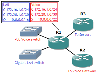
Only this time, at router R1, there’s an extra interface (G0/4), which is used as an internet breakout. You’ve received two public static IP’s on top of the static IP of the router, which you can use. This time, the manager asks that all users connect towards the internet behind one IP address, and that the voice gateway has a static public IP address as well. This gives a problem right away: users and voice server are in a seperate VRF. And an interface can’t be part of more than one VRF. So what do we do with our single internet breakout? Solution: some VRF manipulation, clever placing of the NAT commands, and policy-based routing (PBR). For clarity: towards the ISP we will use 198.15.0.0/30, a point-to-point link, and the two public addresses from the ISP will be 198.15.0.4/31.

First stretching the concept of VRF a bit: an interface can’t be part of more than one VRF, but it can be added to the routing table of multiple VRF. Note that the configuration below is done on a 12.x IOS. 15.x requires different vrf commands (without ‘ip’ in front of it).

R1(config)#interface g0/4
R1(config-if)#ip policy route-map RM-Internet
R1(config-if)#ip vrf receive VOICE
R1(config-if)#ip vrf receive LAN
R1(config-if)#ip address 198.15.0.2 255.255.255.252
R1(config-if)#ip nat outside
R1(config-if)#exit
R1(config)#ip route vrf VOICE 0.0.0.0 0.0.0.0 g0/4 198.15.0.1
R1(config)#ip route vrf LAN 0.0.0.0 0.0.0.0 g0/4 198.15.0.1

The PBR command ‘ip policy’ needs to go first, otherwise ‘ip vrf receive’ will not be accepted and a message “% Need to enable Policy Based Routing on the interface first” will show. The latter places the interface into the VRF routing tables. Together with the default routes for those VRF, it allows for outgoing traffic from both VRF towards the internet.

Now where to place the NAT? Usually this is done in the outside interface. Except, since both VRF have overlapping IP ranges, it can’t always be done there. Instead, on the inside interfaces, inside the VRF, the translation must be made so it’s a unique outside address before it reaches the outside interface.

R1(config)#interface g0/1
R1(config-if)#ip vrf forwarding LAN
R1(config-if)#ip address 172.16.1.1 255.255.255.0
R1(config-if)#ip nat inside
R1(config-if)#exit
R1(config)#interface g0/3
R1(config-if)#ip vrf forwarding VOICE
R1(config-if)#ip address 172.20.1.1 255.255.255.252
R1(config-if)#ip nat inside
R1(config-if)#exit
R1(config)#ip access-list standard AL4-NAT-LAN
R1(config-std-nacl)#permit 172.16.1.0 0.0.0.255
R1(config-std-nacl)#exit
R1(config)#ip nat pool PL-NAT-LAN 198.15.0.4 198.15.0.4 netmask 255.255.255.255
R1(config)#ip nat inside source list AL4-NAT-LAN pool PL-NAT-LAN vrf LAN overload
R1(config)#ip nat inside source static 172.20.1.2 198.15.0.5 vrf VOICE

This gives the users on the LAN an external IP address of 198.15.0.4 and the voice server a static NAT of 198.15.0.5. But while that works for outgoing traffic, incoming traffic still has an issue. How does the router know in which VRF to place the incoming traffic? That’s where the PBR comes into play.

R1(config)#ip access-list extended AL4-IN-LAN
R1(config-ext-nacl)#permit ip any host 198.15.0.4
R1(config-ext-nacl)#exit
R1(config)#ip access-list extended AL4-IN-VOICE
R1(config-ext-nacl)#permit ip any host 198.15.0.5
R1(config-ext-nacl)#exit
R1(config)#route-map RM-IN permit 3
R1(config-route-map)#match ip address AL4-IN-LAN
R1(config-route-map)#set vrf LAN
R1(config-route-map)#route-map RM-IN permit 6
R1(config-route-map)#match ip address AL4-IN-VOICE
R1(config-route-map)#set vrf VOICE
R1(config-route-map)#exit

The above creates a route-map that refers to two ACLs. The goal is simple: if incoming traffic has destination IP addres 198.15.0.4 (NAT for user LAN), then it’s placed in the LAN VRF. If it has 198.15.0.5 (static NAT voice server) as destination IP address, it is placed in the VOICE VRF.

All the above together allow each VRF to use the same internet uplink. The routing table of a VRF looks normal:

R1#show ip route vrf LAN

Gateway of last resort is 198.15.0.1 to network 0.0.0.0

172.16.0.0/24 is subnetted, 1 subnets
C       172.16.1.0 is directly connected, GigabitEthernet0/1
172.20.0.0/30 is subnetted, 1 subnets
C       172.20.1.0 is directly connected, GigabitEthernet0/2
10.0.0.0/16 is subnetted, 1 subnets
O       10.0.0.0 [110/2] via 172.20.1.2, 17:42:38, GigabitEthernet0/2
198.15.0.0/30 is subnetted, 1 subnets
C       198.15.0.0 is directly connected, GigabitEthernet0/4
S*   0.0.0.0/0 [1/0] via 198.15.0.1, GigabitEthernet0/4

This is very useful in an environment with multiple VRF and one internet breakout. However, this can also be used in other cases, such as an MPLS-VPN environment, which Darren covers in detail on his blog.