Tag Archive: NAT


ASA: nice-to-know features.

I’ve already made an introduction to the ASA, but when working with them on a regular basis, it’s nice to know some features that come with the product to explain how it reacts and help troubleshooting. So for the interested reader with little ASA experience, below a few features that have proven handy to me.

Full NAT & socket state
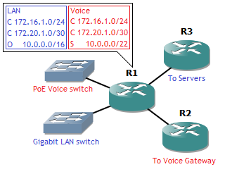
Most consumer-grade routers with NAT keep a NAT state table that keeps state only with the source socket . A socket is an IP address and port paired together. For example, the following setup:

ASA-NAT

When connecting to the web server, remote socket 198.51.100.5:80, a local socket, for example 192.168.1.2:37004 is created. The router will then do a NAT translation to its outside IP address (a NAT/PAT with overloading or hide NAT) to socket 203.0.113.10:37004. This means that if return traffic arrives for destination 203.0.113.10 port 37004, it will be translated to 192.168.1.2 port 37004. However, without stateful firewalling, any packet will be translated back in again on port 37004, regardless of source. This is how some software like torrent programs do NAT hole punching. Also, no matter how big the pool of private IP addresses, the public IP address translations have a maximum of about 64,000 ports available (okay, 65,535 technically but there are probably some reserved and a source port below 1,024 is generally not recommended).

The ASA handles this differently: in combination with the stateful firewall a full state is made for each connection, both source and destination socket. This means the above translation is still done but no return traffic from another source is allowed. On top of that, if another inside host makes a connection towards a different web server, the ASA can reuse that port 37004 for a translation. Return traffic from that different web server will be translated to the other inside host because the ASA keeps a full state. Result: no 64,000 ports per public IP address the device has, but 64,000 per remote public IP address! This allows for even more oversubscription of a single public IP address, assuming not everyone is going to browse the exact same website.

ASA-DoubleSocket

Sequence randomization
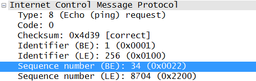
A bit further into layer 4: TCP uses sequence numbers to keep track of the right order in a packet flow. The initial sequence number is supposed to be random, but this is not often the case in practice. In fact, one quick Wireshark from a connection to Google gives me this:

ASA-Sequence

The problem is that guessing sequence numbers allows an attacker to intercept a TCP connection or guess an operating system based on the sequence number pattern. That’s where the second nice-to-know ASA feature comes into play: sequence randomization. By adding a random number to each sequence number (the same random number for each packet per flow) it becomes impossible to guess the initial sequence number of the next connection, as well as difficult to do any OS fingerprinting based on it.

Inspect policy-maps
For someone not familiar with the ASA, this is often a point of trouble. By default the ASA has no awareness above layer 4. This means any information not in the UDP or TCP header isn’t checked. Examples are HTTP headers, the FTP port used for transfer (which is in the payload) and ICMP Sequence numbers.

ASA-ICMP

ASA requires configuration of policy-maps for this. This is why by default ping requests through the ASA don’t work: it cannot create a state for it. And for HTTP inspect, it checks for proper HTTP headers as well as the presence of a user-agent header. This means non-HTTP traffic cannot be sent through port 80, and incoming telnets on port 80 towards web servers aren’t accepted either, preventing some scans.

Capturing
Finally, one of the most useful functions. While many other platforms with a Unix-based OS allow some form of tcpdump, Cisco does not support it. However, you can do some form of capturing on an ASA, even with proper filtering.

First configure the ACL that will be used as a filter, otherwise you’ll capture all traffic for that interface.

ASA#configure terminal
ASA(config)#access-list ExampleCapture extended permit ip host 172.16.16.16 any
ASA(config)#exit

Next, find the correct interface name: the ‘nameif’ because the usual interface name will not do.

ASA#show run int vlan16
!
interface Vlan16
nameif Internal
security-level 50
ip address 172.16.16.1 255.255.255.0

Now you can start and show the capture.

ASA#capture TestCap interface Internal access-list ExampleCapture
ASA#show capture TestCap
76 packets captured

1: 16:45:13.991556 802.1Q vlan#16 P0 172.16.16.249.44044 > 203.0.113.10.22: S 3599242286:3599242286(0) win 8192 <mss 1460,nop,wscale 8,nop,nop,sackOK>
2: 16:45:14.035474 802.1Q vlan#16 P0 172.16.16.249.44044 > 203.0.113.10.22: . ack 1303526390 win 17520
3: 16:45:14.037824 802.1Q vlan#16 P0 172.16.16.249.44044 > 203.0.113.10.22: P 3599242287:3599242338(51) ack 1303526390 win 17520
4: 16:45:14.067196 802.1Q vlan#16 P0 172.16.16.249.44044 > 203.0.113.10.22: . ack 1303526754 win 17156
5: 16:45:14.072887 802.1Q vlan#16 P0 172.16.16.249.44044 > 203.0.113.10.22: P 3599242338:3599242898(560) ack 1303526754 win 17156
6: …

Note that traffic is seen in only one direction here. To see return traffic, add the reverse flow to the capture ACL as well. Unfortunately, the capture must stay running while watching the output here. The capture can be stopped as following:

ASA#no capture TestCap

This will erase the capture also, so the show command will no longer work.

Additionally, you can do a real-time by adding the parameter ‘real-time’, but it’s a bit more tricky. This is not recommended for traffic-intensive flows, but ideal to see if a SYN is actually arriving or not.

ASA#capture TestCap interface External access-list ExampleCapture real-time
Warning: using this option with a slow console connection may
result in an excessive amount of non-displayed packets
due to performance limitations.

Use ctrl-c to terminate real-time capture

1: 16:45:51.755454 802.1Q vlan#16 P0 172.16.16.16.43969 > 203.0.113.10.22: . ack 2670019600 win 16220
2: 16:45:51.768698 802.1Q vlan#16 P0 172.16.16.16.43969 > 203.0.113.10.22: . ack 2670019768 win 17520
3: 16:45:51.768774 802.1Q vlan#16 P0 172.16.16.16.43969 > 203.0.113.10.22: . ack 2670019968 win 17320
4: 16:45:51.777501 802.1Q vlan#16 P0 172.16.16.16.43969 > 203.0.113.10.22: . ack 2670020104 win 17184
5: …

Just don’t forget to remove the ACL after you’re done.

VRF-aware internet breakout.

For this article, let’s continue on a previous one: a basic VRF topology.

VRF

Only this time, at router R1, there’s an extra interface (G0/4), which is used as an internet breakout. You’ve received two public static IP’s on top of the static IP of the router, which you can use. This time, the manager asks that all users connect towards the internet behind one IP address, and that the voice gateway has a static public IP address as well. This gives a problem right away: users and voice server are in a seperate VRF. And an interface can’t be part of more than one VRF. So what do we do with our single internet breakout? Solution: some VRF manipulation, clever placing of the NAT commands, and policy-based routing (PBR). For clarity: towards the ISP we will use 198.15.0.0/30, a point-to-point link, and the two public addresses from the ISP will be 198.15.0.4/31.

First stretching the concept of VRF a bit: an interface can’t be part of more than one VRF, but it can be added to the routing table of multiple VRF. Note that the configuration below is done on a 12.x IOS. 15.x requires different vrf commands (without ‘ip’ in front of it).

R1(config)#interface g0/4
R1(config-if)#ip policy route-map RM-Internet
R1(config-if)#ip vrf receive VOICE
R1(config-if)#ip vrf receive LAN
R1(config-if)#ip address 198.15.0.2 255.255.255.252
R1(config-if)#ip nat outside
R1(config-if)#exit
R1(config)#ip route vrf VOICE 0.0.0.0 0.0.0.0 g0/4 198.15.0.1
R1(config)#ip route vrf LAN 0.0.0.0 0.0.0.0 g0/4 198.15.0.1

The PBR command ‘ip policy’ needs to go first, otherwise ‘ip vrf receive’ will not be accepted and a message “% Need to enable Policy Based Routing on the interface first” will show. The latter places the interface into the VRF routing tables. Together with the default routes for those VRF, it allows for outgoing traffic from both VRF towards the internet.

Now where to place the NAT? Usually this is done in the outside interface. Except, since both VRF have overlapping IP ranges, it can’t always be done there. Instead, on the inside interfaces, inside the VRF, the translation must be made so it’s a unique outside address before it reaches the outside interface.

R1(config)#interface g0/1
R1(config-if)#ip vrf forwarding LAN
R1(config-if)#ip address 172.16.1.1 255.255.255.0
R1(config-if)#ip nat inside
R1(config-if)#exit
R1(config)#interface g0/3
R1(config-if)#ip vrf forwarding VOICE
R1(config-if)#ip address 172.20.1.1 255.255.255.252
R1(config-if)#ip nat inside
R1(config-if)#exit
R1(config)#ip access-list standard AL4-NAT-LAN
R1(config-std-nacl)#permit 172.16.1.0 0.0.0.255
R1(config-std-nacl)#exit
R1(config)#ip nat pool PL-NAT-LAN 198.15.0.4 198.15.0.4 netmask 255.255.255.255
R1(config)#ip nat inside source list AL4-NAT-LAN pool PL-NAT-LAN vrf LAN overload
R1(config)#ip nat inside source static 172.20.1.2 198.15.0.5 vrf VOICE

This gives the users on the LAN an external IP address of 198.15.0.4 and the voice server a static NAT of 198.15.0.5. But while that works for outgoing traffic, incoming traffic still has an issue. How does the router know in which VRF to place the incoming traffic? That’s where the PBR comes into play.

R1(config)#ip access-list extended AL4-IN-LAN
R1(config-ext-nacl)#permit ip any host 198.15.0.4
R1(config-ext-nacl)#exit
R1(config)#ip access-list extended AL4-IN-VOICE
R1(config-ext-nacl)#permit ip any host 198.15.0.5
R1(config-ext-nacl)#exit
R1(config)#route-map RM-IN permit 3
R1(config-route-map)#match ip address AL4-IN-LAN
R1(config-route-map)#set vrf LAN
R1(config-route-map)#route-map RM-IN permit 6
R1(config-route-map)#match ip address AL4-IN-VOICE
R1(config-route-map)#set vrf VOICE
R1(config-route-map)#exit

The above creates a route-map that refers to two ACLs. The goal is simple: if incoming traffic has destination IP addres 198.15.0.4 (NAT for user LAN), then it’s placed in the LAN VRF. If it has 198.15.0.5 (static NAT voice server) as destination IP address, it is placed in the VOICE VRF.

All the above together allow each VRF to use the same internet uplink. The routing table of a VRF looks normal:

R1#show ip route vrf LAN

Gateway of last resort is 198.15.0.1 to network 0.0.0.0

172.16.0.0/24 is subnetted, 1 subnets
C       172.16.1.0 is directly connected, GigabitEthernet0/1
172.20.0.0/30 is subnetted, 1 subnets
C       172.20.1.0 is directly connected, GigabitEthernet0/2
10.0.0.0/16 is subnetted, 1 subnets
O       10.0.0.0 [110/2] via 172.20.1.2, 17:42:38, GigabitEthernet0/2
198.15.0.0/30 is subnetted, 1 subnets
C       198.15.0.0 is directly connected, GigabitEthernet0/4
S*   0.0.0.0/0 [1/0] via 198.15.0.1, GigabitEthernet0/4

This is very useful in an environment with multiple VRF and one internet breakout. However, this can also be used in other cases, such as an MPLS-VPN environment, which Darren covers in detail on his blog.

If you’re working in a large enterprise with its own AS and public range(s), you’ll probably recognize the following image:

MultiClientDataCenter

On top, the internet with BGP routers, peering with multiple upstream providers and advertising the public range(s), owned by the company. Below that, multiple firewalls or routers (but I do hope firewalls). Those devices either provide internet access to different parts of the company network, or provide internet access to different customers. Whatever the case, they will have a default route pointing towards the BGP routers (a nice place for HSRP/VRRP).

Vice versa, the BGP routers have connectivity to the firewalls in the connected subnet, but they must also have a route for each NAT range towards the firewalls. This is often done using static routes: for each NAT range, a static route is defined on the BGP routers, with a firewall as a next hop. On that firewall, those NAT addresses are used, e.g. if the BGP has a route for 192.0.2.0/30, those four (yes, including broadcast and network) addresses can be used to NAT a server or users behind, even if those aren’t present on any interface in that firewall.

The problem in this setup is that it quickly becomes a great administrative burden, and since all the firewalls have a default route pointing towards the BGP routers, traffic between firewalls travels an extra hop. Setting up static routing for all the NAT ranges on each firewall is even more of a burden, and forgotten routes introduce asymmetric routing, where the return path is through the BGP. And while allocating one large public NAT range to each firewall sounds great in theory, reality is that networks tend to grow beyond their designed capacity and new NAT ranges must be allocated from time to time, as more servers are deployed. Perhaps customers even pay for each public IP they have. Can this be solved with dynamic routing? After all, the NAT ranges aren’t present on any connected subnet.

Yes, it’s possible! First, set up a dynamic routing protocol with all routers in the connected public subnet. Personally, I still prefer OSPF. In this design, the benefit of OSPF is the DR and BDR concept: set these to the BGP routers so they efficiently multicast routing updates to all firewalls. Next, on all firewalls, allow the redistribution of static routes, preferably with an IP prefix filter that allows only subnets in your own public IP range, used for NAT. Finally, if you need a NAT range, you just create a Null route on the firewall that needs it (e.g. 192.0.2.0/30 to Null0), and the route will automatically be redistributed into OSPF towards the BGP routers, who will send updates to all other firewalls. Problem solved!

But what about that Null route? Won’t packets be discarded? No, because this is where a particular logic of NAT comes into play: NAT translations are always done before the next hop is calculated. A packet entering with destination address pointing towards a Null route (e.g. 192.0.2.1) will first be translate to the private IP address, after which the route lookup gives a connected subnet or another route further into the private network. The Null route is never actually used!

Most network engineers with some experience know the RFC 1918 address space from the top of their head. No need to explain the use: to counter IPv4 address shortage, you put multiple hosts in a private subnet behind one public IP address.

NAT44

While this does help against the shortage, a lot of routers performing NAT inside a service provider network still use a lot of addresses. For this reason, a provider can implement Carrier-Grade NAT (CGN). CGN does a NAT of the addresses of all these routers towards one or a few public IP addresses, hereby saving once more a lot of public address space.

But what address space should be used here? Obviously no public space, that would defeat the purpose. But RFC 1918 address space is not an easy option either: if one of the NAT-performing routers has the same subnet on the inside as on the outside (the outside being the service provider network here), no routing will be possible for this network. Since a service provider has no view on which RFC 1918 address space is exactly used by the end users, an overlap is possible.

This is where RFC 6598 comes into the picture. This RFC allocates an IPv4 prefix that can be used for internal addressing, separately from the RFC 1918 addresses. Result: no overlap, yet no use of publicly routable addresses. The chosen prefix is 100.64.0.0/10.

NAT444

Why an entire /10 range if addresses are so scarce already? The RFC mentions a /10 is the smallest prefix that would provide an address to all service points in the Greater Tokyo Area, the largest metropolitan area in the world.

The advantage is obvious, less public IPv4 addresses used. But this technique comes with mayor drawbacks:

  • The service provider router performing CGN needs to maintain a state table for all the address translations: this requires a lot of memory and CPU resources.
  • Tracking of users for legal reasons means extra logging, as multiple households go behind one public address.
  • Some NAT-discovering applications recognize NAT based on RFC 1918 addresses and may be unable to figure out the topology with the new address range.
  • Anything requiring incoming connections is broken. While this already was the case with regular NAT, end users could usually still set up port forwarding on their NAT router. CGN makes this impossible. This means no web servers can be hosted here, and IP Phones cannot receive incoming calls by default either.
  • Many networks and service providers (should) have access lists on the network boundaries preventing any IP packets with RFC 1918 addresses from entering the network to prevent spoofing attacks. If these access lists aren’t updated, IP packets with RFC 6598 addresses can enter the network.
  • Some web servers only allow a maximum number of connections from the same public IP address, as a means to counter DoS attacks like SYN floods. Using CGN this limit is reached more often and some services may be of poor quality in a CGN network.

A CGN network is also often referenced to as a NAT444 network, as opposed to a NAT44 network for a ‘normal’ NAT environment, because three different IPv4 address spaces are involved.

While this address range is something you’ll not likely encounter unless you’re working for a service provider, it is important because of the IP spoofing implications and it provides an alternative when working in a double-NAT environment.

It’s been a while since I’ve posted anything since I’ve been very busy with lots of personal things.  Until a few days ago, when I needed to set up an ASA urgently as a stateful firewall to protect a web server. The perfect basic setup, but still a challenge for someone inexperienced. So below some brief notes to get an ASA going with basic firewall functionality.

First step: basic configuration of the interfaces. The ASA5505 interfaces work somewhat like a layer 3 switch, with VLAN interfaces and switchports, that can be configured in access, trunk or routed interface mode. Other ASA models work more like a router, with layer 3 interfaces, and subinterfaces for trunk link behavior.
In this example, the first interface on my ASA5505 will become a routed interface for out-of-band access in a 10.0.3.0/24 subnet, the second interface will also be routed and become the external connection with IP 20.30.40.50 (ISP gateway 20.30.40.1), and the remaining interfaces will be switchports part of VLAN 5 with subnet 192.168.3.0/24 as the internal network.

ASA5505#configure terminal
ASA5505(config)#interface Ethernet0/0
ASA5505(config-if)#no switchport
ASA5505(config-if)#ip address 10.0.3.2 255.255.255.0
ASA5505(config-if)#description Management
ASA5505(config-if)#nameif MGMT
ASA5505(config-if)#security-level 100
ASA5505(config-if)#management-only
ASA5505(config-if)#exit
ASA5505(config)#interface Ethernet0/1
ASA5505(config-if)#no switchport
ASA5505(config-if)#ip address 20.30.40.50 255.255.255.0
ASA5505(config-if)#description ISP
ASA5505(config-if)#nameif External
ASA5505(config-if)#security-level 0
ASA5505(config-if)#exit
ASA5505(config)#interface Vlan 5
ASA5505(config-if)#ip address 192.168.3.1 255.255.255.0
ASA5505(config-if)#nameif Internal
ASA5505(config-if)#security-level 50
ASA5505(config-if)#exit
ASA5505(config)#interface range Ethernet0/2 – 7
ASA5505(config-if)#switchport mode access
ASA5505(config-if)#switchport access vlan 5
ASA5505(config-if)#exit

Some explanations here: the ‘nameif’ gives the interface an actual name that can be seen in ASDM and worked with for all firewall rules to come. The security-level is used by the ASA to determine which interface is considered a safe-zone, and which one is not. By default, traffic from safer interfaces (higher security-level) can flow to less secure interfaces, but not the other way around (except for the return packets of stateful connections). Equal security-level interfaces can’t pass traffic between each other by default, but this option can be toggled in the ASDM, or by the ‘same-security-traffic permit inter-interface’ command. Also, the ‘management-only’ command on the management interface prevents that interface from being part of the routing, so no packets from and to any other interface can be passed through this interface.

Next is setting up a local user account for SSH and ASDM access, as well as an enable password. Consider this mandatory for any ASA.

ASA5505(config)#user reggle privilege 15 password ********
ASA5505(config)#enable password ********
ASA5505(config)#aaa authentication ssh console LOCAL
ASA5505(config)#ssh 0.0.0.0 0.0.0.0 MGMT
ASA5505(config)#http server enable
ASA5505(config)#http 0.0.0.0 0.0.0.0 MGMT
ASA5505(config)#asdm image disk0:/asdm-645-206.bin

Again more explanation: the third line makes sure the local username database is used when trying to log in on SSH. RADIUS and TACACS+ are also possible of course, but I’m not going to cover that here. The fourth and sixth line define who may connect to SSH and ASDM, respectively. In this case I allow access from any IP (0.0.0.0/0), but only on the Management interface, which is defined by the nameif configured earlier. You can add multiple lines with multiple subnets and interfaces, but this is a basic example.

The last line is also required or ASDM will not work. It defines where on the local system the ASDM installation file is located. The file has to be present! The version may differ of course and can be downloaded on the Cisco website. The positive side of this is that once all of this is configured, you can connect to the ASA with your browser and it will provide you with a download link for ASDM if you don’t have it installed already. This can save you a lot of searching when you urgently need to log in from a computer that doesn’t have this installed yet. Note that ASDM does require a modern 32-bit Java to function, even on 64-bit operating systems.
The last thing I do in the console after this is setting up basic static routing: a  default route towards the internet on the External interface. The Management interface is a bit trickier and I haven’t worked that one out yet: everything in the local 10.0.3.2 subnet can connect, but I haven’t tested if setting a default route for the Management interface actually works, so I’m not going to define one here.

ASA5505(config)#route External 0.0.0.0 0.0.0.0 20.30.40.1

That’s the end of the console part. For firewalling and NAT, I prefer the ASDM now. Logging in is done by surfing to https://10.0.3.2 and giving the username and password configured earlier. It’s an easy to understand interface. First NAT, which you can find under ‘Configuration’ in the menu above, then ‘Firewall’ on the left, and finally ‘NAT rules’, also on the left. There you can add new rules on the interfaces.

ASDM-NAT

In the NAT rule menu, you can add objects (which you can create there too) that must be translated. For example, a dynamic or hide NAT of the 192.168.3.0/24 network behind the address of the External interface, 20.30.40.50. Static NAT rules for servers are also possible and you can NAT those behind addresses not configured on any interface, for example if you’ve received a range to use from your provider or own an IP range. In the last case, make sure routing (likely BGP for your own IP range) is pointing towards the ASA for the IP’s you’re going to use.

When your changes are done, you can click apply on the bottom of the screen to push the configuration towards the ASA. The ‘Save’ button on top of the screen acts the same as ‘copy run start’.
Next, under ‘Access rules’ on the left you can define the actual firewall rules. Again the same simple interface to add objects in rules, source, destination, ports, time frames,… I’m not going to explain in detail, it’s easy to experiment with should you have the chance to do so. A few points to keep in mind though:

  • The rules are examined top-down. So if the first rule denies something, even a dozen allow rules after that will not change the decision.
  • Top-down means it takes CPU to match something on the bottom of a long rule list. Luckily, the ASA shows the number of hits on each rule in the ASDM, so you can place the most-used rules on top of the rule list to reduce CPU load.
  • When defining an object, use netmask 255.255.255.255 to define a single IP.
  • If you’re using NAT on an external interface, don’t define any rule on that interface with the internal IP address of a NAT rule. It will of course not match any incoming packet.
  • I’m very fond of how easy the ASDM interface is, but keep in mind this is a GUI which pushes configuration towards a device. This push action can be interrupted, which may result in missing rules or configurations. So for larger configurations, it can’t hurt to push ‘Apply’ twice from time to time.

This configures a basic ASA firewall. Biggest challenge after the configuration: connecting the cables correctly!

In my previous post I described how to set up OpenBSD and enable simple routing between interfaces. This time an explanation about one of the core features: pf, or packet filter.

The pf service allows for stateful firewalling and NAT translations when routing. Starting where we took off in part I, we have an OpenBSD 5.0 with routing enabled and interfaces configured. pf is one of the few things to be active by default, so it’s already running now, but it doesn’t do anything as no rules have been defined yet. Defining rules has to be done in /etc/pf.conf . How? Again, by using a text editor like vi. Yes, that’s ‘vi /etc/pf.conf’ on the command line. There are already some basic rules defined in pf.conf, most of them commented out as examples.

A filtering rule consists of several keywords. A complete guide is available as a manual page, but I’ll list the basics here:

  • Most used are pass and block. The first permits a packet based on parameters defined further in the rule, the second drops the packet.
  • Next is in or out. Either filter incoming or outgoing on an interface. Incoming takes place before a route look-up so filtering mostly on incoming will take less CPU.
  • This one is optional: quick. Without it, pf will check all rules and treat a packet according to the last matching rule. However, if a rule contains the word quick and the packet matches, any following rules are no longer checked. Using this keyword makes the filtering behave more like a Cisco ACL (top-to-bottom), and will take less CPU as not all rules have to be examined every time.
  • on, followed by an interface, e.g. em0. It defines on which interface the filtering takes place.
  • proto, followed by a protocol, mostly tcp, udp or icmp. It’s an optional keyword: if it’s missing, filtering will be done with layer 3 information (IPv4, IPv6) only.
  • from defines where from. It can be any, an ip, or a subnet, e.g. 10.0.1.0/24.
  • port is optional after this and defines the source port(s). It uses operators, e.g. port = 2000 is port 2000, port < 5000 is any port below 5000, and so on. Since it’s a source port and most applications use dynamic source ports, this isn’t used that much.
  • to defines the destination host or subnet. Same parameters as from.
  • A second port, again optional, after to. This is the destination port. Since these are usually well-known ports, it’s often used.

Many more options and keywords are possible, but knowing the above is sufficient for decent stateful firewalling.

The second part is address translation, or NAT. A basic setup is as following:

  • match is the first keyword. You can also use pass, but it will pass everything unless you define certain ports in the rule also.
  • Next are in or out, with out being the most used (and easiest to troubleshoot too, in my opinion).
  • Then: on for the interface, from and to. proto and port are optional.
  • Last: nat-to, followed by an (external) IP. It defines what the host or subnet defined in from will NAT to.

We can try this in an example. Let’s assume the OpenBSD has interface em0 connected to an ISP (IP 1.2.3.4) and em1 to an internal network 192.168.168.0/24. This shows what can be done with it:

match out quick on em0 from 192.168.168.0/24 to any nat-to 1.2.3.4

pass out quick on em0 proto tcp from 1.2.3.4 to any port = 80
pass out quick on em0 proto udp from 1.2.3.4 to 8.8.8.8 any port = 53
block out on em0

The above will NAT any internal address from em1 to the external IP. Everything will be blocked (the last rule), except TCP traffic to port 80 (which is http traffic) and UDP port 53 to IP 8.8.8.8 (which are DNS requests to the IP of Google’s DNS).

The above works, but it’s a very incomplete example of course: no https (port 443) is possible for example, as are pings and the ability to choose another DNS server in case of a DNS problem. But it demonstrates the point. Don’t forget to do ‘:wq’ to save your changes!

Now just one more thing: these rules aren’t activated by default: you’ll need ‘pfctl -nf /etc/pf.conf’ and ‘pfctl -f /etc/pf.conf’. The first commands checks if the rules don’t contain any syntax errors, which you should always check, and the second command loads the rules in the current configuration.

A simple honey pot test.

Security today. I’ve done some testing with a honey pot. What is a honey pot? It’s a (network) construction you make to lure in hack attempts and/or malware. You can use it for early detection of threats, analysing attacker behaviour, or drawing away attention from the real target.

There are several ways to set up a honey pot, depending on what you want. Inside an enterprise, you can set up a server that acts just like a real production device, but it’s not providing any real services and instead is logging every attack against it. Allocating an empty subnet, then logging everything that enters that subnet is also a good method: an empty subnet is supposed to be untouched, so anything entering it may be scanning for targets.

My method is similar to the ones above, except I don’t have a free subnet to allocate. But the NAT router I have has a DMZ option. In practice this does the following: any port or protocol that’s not in use by another device on the private subnet, will be forwarded to the IP defined in DMZ. Example: PC 2 is set in DMZ, internal IP 192.168.168.2. All other PCs use the NAT router to access internet. This means that if PC 2 makes a connection to a web server, source port 33502, destination port 80, the web server will reply from port 80 to port 33502 again. The NAT router then forwards port 33502 to PC 2 because it was opened by PC 2. But if something enters on port 33503 and that port has not been opened by an inside device, it will be forwarded to PC 1, who will then log it.

Honeypot

For logging I used a Windows XP with Wireshark. The Windows XP had static IP 192.168.168.2, correct subnetmask, but no gateway. Why? Because I want to do passive logging and the logging device should be unable to respond back, especially since it had no firewall and received everything unfiltered. On Wireshark I set up a filter to only capture unicast packets to its own static IP, filtering away background noise. The only problem is that my ISP blocks off any incoming port below 1024, meaning I will not see any connection attempts on most well-known ports, so I had no big expectations.

I kept it running all night, a total of 14 hours and 30 minutes. And the next day, Wireshark indeed reported several captured packets. Here’s what I found:

  • 50 hits for incoming destination UDP port 12148. Mostly IPs from Europe, some from North and South America, random source ports. I have no idea what this means, as port 12148 doesn’t have any registered service to it.
  • 65 hits for TCP SYN on destination port 12148. Again randomly throughout the night, random IPs and source ports. No recognizable pattern, and no relation to the UDP packets. Still, no idea.
  • 15 hits for destination UDP port 1030. Not officially registered, but it seems to be used as a loopback port for exchanging information between software components in Windows. All from the same IP – somewhere in Poland – but random throughout the night, sometimes with hours between. Not sure if this is indeed an attempt of some sort, or just a confused device somewhere in Poland.
  • 4 hits with source UDP port 53, DNS, to a random destination port. Three IPs, all from (anycast) DNS servers I don’t use. Message content is ‘format error’ or ‘server failure’. Probably not an attempt for something but consequence of some malconfigured device somewhere, I think.
  • 3 ping requests. Because of the missing gateway on my honey pot, no reply. All three occurred from different locations around the world and consisted of two pings with exactly 2.2 seconds between them. Strong indication the same tool is being used here, and likely an attempt to check if anything is alive on my IP.
  • 1 hit for UDP destination port 1434 – SQL. From China. That’s an attempt alright.

That’s 4 packets over 14 hours which are used to scan for weaknesses: 3 ping, 1 SQL. Not taking into account anything below 1024. Not much, but enough to prove the necessity for firewalling.

Extra information: to look up the geographical location of each IP, I used http://www.ipligence.com/geolocation

Everytime I see private range addresses somewhere, I automatically think about Network Address Translation. But NAT and private addresses do not always need to be used together.

Take the following network:

Example network

Now suppose you have received a /22 public address range for your company, e.g. 123.45.68.0/22, which you then split up in subnets for your users and servers. Since IPv4 addresses are limited and you have three point-to-point links in the ‘Internal’ part of the network, you’re hesistant to go waste 12 addresses (three times a /30) on them. Sure you could use /31’s and use only 6 IP’s, but if the number of links increases, so do the wasted IP’s.

But if you give these links IP’s in the ranges 192.168.1.0/30, 192.168.1.4/30 and 192.168.1.8/30 and advertise them internally with whatever IGP you’re using, things will work too. You will need to filter any packets originating from these private ranges at the WAN edge router so they don’t reach the internet. Any hosts on the internet can’t reach the IP’s on the point-to-point links as they aren’t advertised to outside the company (added security!). Internally in your network, the private ranges become part of the network, without NAT. They can be pinged perfectly. You could even set up a subnet using private ranges for servers that must only be accessed internally (very secure, though automatic updates would not be so easy, I can imagine). For remote connectivity, VPN should allow access.

All in all, a real world implementation by this design may have some flaws, but it proves a point, and adds security in some sense.