Tag Archive: Cisco


This article is not really written with knowledge usable for a production network in mind. It’s more of an “I have not failed. I’ve just found 10,000 ways that won’t work.” kind of article.

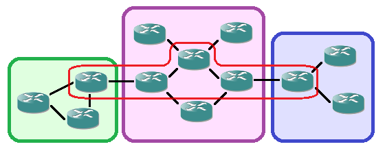
I’m currently in a mailing group with fellow network engineers who are setting up GRE tunnels to each others home networks over the public internet. Over those networks we speak (external) BGP towards each other and each engineer announces his own private address range. With around 10 engineers so far and a partial mesh of tunnels, it gives a useful topology to troubleshoot and experiment with. Just like the real internet, you don’t know what happens day-to-day, neighborships may go down or suddenly new ones are added, and other next-hops may become more interesting for some routes suddenly.

SwitchRouting1

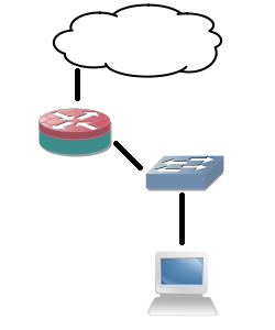
But of course it requires a device at home capable of both GRE and BGP. A Cisco router will do, as will Linux with Quagga and many other industrial routers. But the only device I currently have running 24/7 is my WS-C3560-8PC switch. Although it has an IP Services IOS, is already routing and can do GRE and BGP, it doesn’t do NAT. Easy enough: allow GRE through on the router that does the NAT in the home network. Turns out the old DD-WRT version I have on my current router doesn’t support it. Sure I can replace it but it would cost me a new router and it would not be a challenge.

SwitchRouting2

Solution: give the switch a direct public IP address and do the tunnels from there. After all, the internal IP addresses are encapsulated in GRE for transport so NAT is required for them. Since the switch already has a default route towards the router, set up host routes (a /32) per remote GRE endpoint. However, this still introduces asymmetric routing: the provider subnet is a connected subnet for the switch, so incoming traffic will go through the router and outgoing directly from the switch to the internet without NAT. Of course that will not work.

SwitchRouting3

So yet another problem to work around. This can be solved for a large part using Policy-Based Routing (PBR): on the client VLAN interface, redirect all traffic not meant for a private range towards the router. But again, this has complications: the routing table does not reflect the actual routing being done, more administrative overhead, and all packets originated from the local switch will still follow the default (the 3560 switch does not support PBR for locally generated packets).

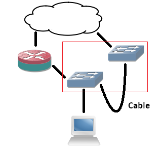
Next idea: it would be nice to have an extra device that can do GRE and BGP directly towards the internet and my switch can route private range packets towards it. But the constraint is no new device. So that brings me to VRFs: split the current 3560 switch in two: one routing table for the internal routing (vrf MAIN), one for the GRE tunnels (vrf BGP). However, to connect the two VRFs on the same physical device I would need to loop a cable from one switchport to another, and I only have 8 ports. The rest would work out fine: point private ranges from a VLAN interface in one VRF to a next-hop VLAN interface over that cable in another VRF. That second VRF can have a default route towards the internet and set up GRE tunnels. The two VRFs would share one subnet.

SwitchRouting4

Since I don’t want to deal with that extra cable, would it be possible to route between VRFs internally? I’ve tried similar actions before, but those required a route-map and a physical incoming interface. I might as well use PBR if I go that way. Internal interfaces for routing between VRFs exist on ASR series, but not my simple 8-port 3560. But what if I replace the cable with tunnel interfaces? Is it possible to put both endpoints in different VRFs? Yes, the 15.0(2) IOS supports it!

SwitchRouting5

The tunnel interfaces have two commands that are useful for this:

  • vrf definition : just like on any other layer 3 interface, it specifies the routing table of the packets in the interface (in the tunnel).
  • tunnel vrf :  specifies the underlying VRF from which the packets will be sent, after GRE encapsulation.

With these two commands, it’s possible to have tunnels in one VRF transporting packets for another VRF. The concept is vaguely similar to MPLS-VPN,  where your intermediate (provider) routers only have one routing table which is used to transport packets towards routers that have the VRF-awareness (provider-edge).

interface Vlan2
ip address 192.168.2.1 255.255.255.0
interface Vlan3
ip address 192.168.3.1 255.255.255.0
interface Tunnel75
vrf forwarding MAIN
ip address 192.168.7.5 255.255.255.252
tunnel source Vlan2
tunnel destination 192.168.3.1
interface Tunnel76
vrf forwarding BGP
ip address 192.168.7.6 255.255.255.252
tunnel source Vlan3
tunnel destination 192.168.2.1

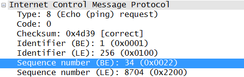
So I configure two tunnel interfaces, both in the main routing table. Source and destination are two IP addresses locally configured on the router.  I chose VLAN interface, loopbacks will likely work as well. Inside the tunnels, one is set to the first VRF, the other to the second. One of the VRFs may be shared with the main (outside tunnels) routing table, but it’s not a requirement. Configure both tunnel interfaces as two sides of a point-to-point connection and they come up. Ping works, and even MTU 1500 works over the tunnels, despite the show interface command showing an MTU of only 1476!

Next, I set up BGP to be VRF-aware. Logically, there are two ‘routers’, one of which is the endpoint for the GRE tunnels, and another one which connects to it behind it for internal routing. Normally if it were two physical routers, I would set up internal BGP between them since I’m already using that protocol. But there’s no difference here: you can make the VRFs speak BGP to each other using one single configuration.

router bgp 65000
address-family ipv4 vrf MAIN
neighbor 192.168.7.6 remote-as 65000
network 192.168.0.0 mask 255.255.248.0
neighbor 192.168.7.6 activate
exit-address-family
address-family ipv4 vrf BGP
bgp router-id 192.168.7.6
neighbor 192.168.7.5 remote-as 65000
neighbor 192.168.7.5 activate
exit-address-family

A few points did surface: you need to specify the neighbors (the IP addresses of the local device in the different VRFs) under the correct address families. You also need to specify a route distinguisher under the VRF as it is required for VRF-aware BGP. And maybe the most ironic: you need a bgp router-id set inside the VRF address-family so it differs from the other VRF (the highest interface IP address by default), otherwise the two ‘BGP peers’ will notice the duplicate router-id and it will not work. But after all of that, BGP comes up and routes are exchanged between the two VRFs! For the GRE tunnels towards the internet, the tunnel vrf command is required in the GRE tunnels so they use the correct routing table for routing over the internet.

So what makes this not production-worthy? The software-switching.

The ASIC can only do a set number of actions in a certain sequence without punting towards the switch CPU. Doing a layer 2 CAM table lookup or a layer 3 RIB lookup is one thing. But receiving a packet, have the RIB pointing it to a GRE tunnel, encapsulate, decapsulate and RIB lookup of another VRF is too much. It follows the expected steps in the code accordingly, the IOS software does not ‘see’ what the point is and does not take shortcuts. GRE headers are actually calculated for each packet traversing the ‘internal tunnel’ link. I’ve done a stress test and the CPU would max out at 100% at… 700 kBps, about 5,6 Mbps. So while this is a very interesting configuration and it gives an ideal situation to learn more, it’s just lab stuff.

So that’s the lesson, as stated in the beginning: how not to do it. Can you route between VRFs internally on a Cisco switch or router (not including ASR series)? Yes. Would you want to do it? No!

I passed the ARCH exam!

It’s been a while since I’ve posted something here. Multiple reasons of course, but lately I just had to focus on learning so much I didn’t take the time for it anymore. Why? Well since I got my CCNP almost three years ago, it had to be recertified. Together with my CCDA that presented the opportunity to gain a CCDP certification and renewing my CCNP at once by just taking one more exam: ARCH.

So it’s been done. Was it hard? I honestly don’t know. So much has changed this last year for me: how I look at my profession, how I look at learning, at certifications,… I can’t compare it anymore to past experiences. So many things I learned outside of the certification path that are so important to have insights as an engineer… Examples like TCP Windowing, ASIC behavior, VRF deployment, application behavior in LAN and WAN (Citrix, SCP, FTP, NTP, vMotion, SCCM), load balancing and SSL offloading, …

All I know that this was a lot of (useful) theory and I had to devise a plan to learn it all, which eventually succeeded. So besides the certification I improved my ability to learn with it. And that in turn gives me strength for the next one: CCIEv5.

Yes, there I said it. For over a year I kept doubting it a bit, saying I wanted it but not putting a date on it. That’s over now. In a month I’ll start preparing the written with hopefully the exam in the first quarter of 2015.

I am ready.

Disclaimer: the logs are taken from a production network but the values (VLAN ID, names) are randomized.

Recently, I encountered an issue on a Campus LAN while performing routine checks: spanning tree seemed to undergo regular changes.

The LAN in question uses five VLANs and RPVST+, a Cisco-only LAN. At first sight there was no issue:

BPDU-Trace1

On an access switch, one Root port towards the Root bridge, a few Designated ports (note the P2P Edge) where end devices connect, and an Alternative port in blocking with a peer-to-peer neighborship, which means BPDUs are received on this link.

There is a command that allows you to see more detail: ‘show spanning-tree detail’. However, the output from this command is overwhelming so it’s best to apply filters on it. After some experimenting, filtering on the keywords ‘from’,’executing’ and ‘changes’ seems to give the desired output:

BPDU-Trace2

This gives a clear indication of something happening in the LAN: VLAN 302 has had a spanning-tree event less than 2 hours ago. Compared to most other VLANs who did not change for almost a year, this means something changed recently. After checking the interface on which the event happened, I found a port towards a desk which did not have the BPDU Guard enabled, just Root Guard. It was revealed that someone regularly plugged in a switch to have more ports, which talked spanning-tree but with a default priority, not claiming root. As such, Root Guard was not triggered, but the third-party switch did participate in spanning-tree from time to time.

Also, as you notice in the image, VLAN 304 seemed to have had a recent event to, on the Alternative Port. After logging in on the next switch I got the following output:

BPDU-Trace3

Good part: we have a next interface to track. Bad news: it’s a stack port? Since it’s a stack of 3750 series switches, it has stack ports in use, but the switches should act as one logical unit in regards to management and spanning-tree, right? Well, this is true, but each switch still makes the spanning-tree calculation by itself, which means that it can receive a spanning-tree update of another switch in the stack through the stack port.

Okay, but can you still trace this? You would have to be able to look in another switch in the stack… And as it turns out, you can:

BPDU-Trace4

After checking which stack port connects to which switch in the CLI, you can hop to the next one with the ‘session’ command and return to the master switch simply by typing ‘exit’. On the stack member, again doing the ‘show spanning tree detail’ command shows the local port on which the most recent event happened. And again the same thing: no BPDU Guard enabled here.


Just a simple article about something I recently did in my home network. I wanted to prepare the network for a Squid proxy, and design it in such a way that the client devices did not require proxy settings. Having trouble placing it inline, I decided I could use WCCP. However, that requires separate VLANs.

This did pose a problem: my home router did not support any kind of routing and multiple networks beyond a simple hide NAT (PAT) behind the public IP address. Even static routes weren’t possible.

And again my fanless 3560-8PC helped me out. The 3560 can do layer 3 so you can configure it with the proper VLANs and use it as the default gateway on all VLANs. Then you add another VLAN towards the router and point a default route towards that router.

That solves half of the problem: packets get to the router and out to the internet. However, the router does not have a return route for the VLANs. But it does not need that: you can use Proxy ARP. As the router will use a /24 subnet, you can subnet all VLANs inside that /24, e.g. a few /26 and a /30 for the VLAN towards the router, as my home network will not grow beyond a dozen devices in total. Now the router will send an ARP request for each inside IP address, after which the layer 3 switch answers on behalf of the client device. The router will forward all data to the layer 3 switch, who knows all devices in the connected subnets.

ProxyARP

And problem solved. From the point of view of the router, there’s one device (MAC address, the layer 3 switch) in the entire subnet that uses a bunch of IP addresses.

IS-IS part II: areas and backbone.

Given the basics covered in part I, IS-IS configuration isn’t that hard. It already clearly shows some differences with OSPF, but it’s when using multiple areas that there is a clear distinction in logic.

OSPF-Areas

First a small recap of OSPF areas: you have a backbone area, area 0, to which all other areas must connect. A router can be in multiple areas, an interface can be in only one area for a given OSPF process. Routes between areas are known by default, but setting an area to stub can change this to just a default route.

ISIS-Areas

IS-IS is different: as you may have guessed by the ‘net’ command of part I, a router can only be part of one area. Area borders are between routers. An area is made up of routers with level 1 neighborships. A router with a level 2 neighborship towards another router is considered a backbone router. Since level 2 neighborships can be between routers in different areas (the second part of ‘net’ command can differ), these routers connect areas.

The moment a router has a level 2 neighborship and becomes a backbone router, it will automatically propagate a default route towards its level 1 neighbors. This gets flooded throughout the area. To reach another area, packets will be sent automatically towards the nearest backbone router. The Backbone router has a second topology table for level 2 that lists information of all subnets in all areas (which requires more memory). The packet will then be transported over the backbone to the appropriate area. For this reason, the backbone must be continuous: otherwise there would be multiple islands of routers propagating default routes.

From that point of view, the level 2 backbone becomes an overlay on top of the areas that connects everything: an extra ‘level’, likely the reason for the terminology. While this design works and is very scalable it may introduce suboptimal routing. Inter-area traffic will go to the nearest backbone router, but there may be other backbone routers in the area that can route the packets to the destination in a better way. For example, in the above image, the bottom router in the purple middle area may decide to follow the default route to the left backbone router for a packet destined for the right blue area.

Configuration is still straightforward:

Router(config)#interface GigabitEthernet0/1
Router(config-int)#ip address 10.0.2.5 255.255.255.252
Router(config-int)#ip router isis
Router(config-int)#isis circuit-type level-1
Router(config-int)#exit
Router(config)#interface GigabitEthernet0/2
Router(config-int)#ip address 10.0.3.1 255.255.255.252
Router(config-int)#ip router isis
Router(config-int)#isis circuit-type level-2-only
Router(config-int)#exit
Router(config)#interface GigabitEthernet0/3
Router(config-int)#ip address 10.0.2.9 255.255.255.252
Router(config-int)#ip router isis
Router(config-int)#
Router(config-int)#exit
Router(config)#router isis
Router(config-router)#log-adjacency-changes
Router(config-router)#net 49.0001.0000.0000.0008.00

This example configures a router for a level 1 neighborship on Gi0/1 (inside the area), a level 2 neighborship on Gi0/2 (between areas) and a level 1 & 2 neighborship on Gi0/3 (inside the area, but still backbone). Note the missing ‘is-type’ command in the routing process, which makes the router default to both a level 1 and level 2 router. A router in another area has a different area number in the net command:

Router(config)#interface GigabitEthernet0/2
Router(config-int)#ip address 10.0.3.2 255.255.255.252
Router(config-int)#ip router isis
Router(config-int)#isis circuit-type level-2-only
Router(config-int)#exit
Router(config)#router isis
Router(config-router)#log-adjacency-changes
Router(config-router)#net 49.0002.0000.0000.0009.00

Note that an IS-IS router is not required to have a level 1 neighborship. It is possible to have a ‘pure’ backbone router with only level 2 neighborships, which makes the router only use one topology table again, just like a level 1-only router.

The topology tables for both levels can be checked with show isis topology l1 and show isis topology l2. Same for the database, just replace the word ‘topology’ with ‘database’. The show clns is-neighbors and show isis neighbors commands both show all IS-IS neighbors and the level of the neighborship.

IS-IS, or Intermediate System to Intermediate System. Just like OSPF, it’s a link-state routing protocol. This article took me quite a bit of research, and things were confusing for me at first because I kept looking at it from an OSPF point of view. Now that I’ve cleared that up for myself, I’ll do my best to explain it here for people knowing OSPF but not IS-IS (which, I assume, will be the majority of readers here).

First some explanation about why one would want to use IS-IS in the first place. After all, both are link-state routing protocols and OSPF is much more familiar to most. However, there are a few key differences in design of the protocols. But the most important reason to choose IS-IS over OSPF is scalability. IS-IS scales to larger topologies compared to OSPF using the same resources. A general recommendation for the number of OSPF routers in an area is between 70 and 100 maximum, while IS-IS will do 150 routers in an area (of course, the number of uplinks, routes and type of routers will influence this number). The difference in multi-area design can also make IS-IS more suitable for some topologies (which I will explain in part II later on).

This part will focus on a single area and basic configuration. It is useful to know some historical facts which explain the difference in commands compared to OSPF.

  • Since IS-IS wasn’t designed with IP in mind but CLNS, it works directly on layer 2 with no IP headers. It uses flexible TLV (Type-Length-Value) fields in the PDUs it exchanges which makes it suitable for carrying routing information of just about any protocol. This is why it’s also used for IPv6 and even TRILL and FabricPath (which is actually nothing more than exchanging the location of MAC addresses by routing protocol).
  • IS-IS has a concept of areas but refers to it as ‘levels’. On a Cisco router the IS-IS routing protocol will try to form neighborships for both level 1 and level 2 by default. When using just one area, it’s best to configure the routing protocol to form neighborship of level 1 only (again, multi-area will be covered in part II).
  • A Network Entitity Title (NET) is used to identify a router. It is made up of four parts: the first byte is an Authority and Format Identifier (AFI),  next two bytes that define the area, followed by six bytes that act as a unique identifier (much like an OSPF router-id) and one byte for n-selector (NSEL). This NSEL is always set to zero for IS-IS for IP (non-zero values are used for actual data transport over CLNS, which likely isn’t used anywhere anymore). The AFI must be officially registered but 49 can be used for internal addressing.
  • As a consequence, the first six bytes (AFI and area ID) have to be the same for all IS-IS routers in an area, and the following six bytes have to be unique for each IS-IS router in an area.
  • For the unique ID part, several methods exist: you can use the system base MAC address, map an IP address to it, or simply start counting from 1 and up.

ISIS-NET

Given all the above, the basic IS-IS routing process can be configured as following:

Router(config)#router isis
Router(config-router)#log-adjacency-changes
Router(config-router)#is-type level-1
Router(config-router)#net 49.0001.0000.0000.0017.00

Unlike the other routing protocols, logging of adjacencies is not on by default on a Cisco router.

Now that the process is configured, interfaces must be added to it. That’s right, interfaces, no ‘network’ command to define subnets. This can be done in two ways:

  • Configuring an IP address on an interface, followed by the ‘ip router isis’ command will make the interface participate.
  • Configuring an IP address on an interface and defining that interface as passive in the router process will make IS-IS announce the subnet on the attached interface but not form any neighborships on it. The ‘ip router isis’ command is not required.

Router(config)#interface GigabitEthernet0/1
Router(config-int)#ip address 10.0.2.1 255.255.255.252
Router(config-int)#ip router isis
Router(config-int)#exit
Router(config)#interface Loopback0
Router(config-int)#ip address 10.0.10.14 255.255.255.255
Router(config-int)#exit
Router(config)#router isis
Router(config-router)#passive-interface Loopback0

And that’s it. Configure this on two adjacent routers and an IS-IS neighborship will form. You can check this using ‘show clns neighbors’ and ‘show isis neighbors’.

ISIS-Show

In upcoming parts, I’ll explain multi-area design and configuration and fine tuning of the default parameters. And for those interested, I’ve uploaded a capture of the IS-IS neighborship forming on Cloudshark.

On this blog I’ve often covered Private VLANs: how to configure them, work around them and deploy them in a larger network. Yet it’s rarely that you see an actual Private VLAN in a design. Part of the problem is covered in the article about deployment over multiple switches: you can’t connect a trunked device such as a firewall to it. Although the Nexus 7000 provides a solution, that doesn’t make it much easier (or cheaper).

Another important reason is that few are willing to take the risk to deploy a VLAN where hosts cannot communicate with each other, as this is usually the reason hosts are put in the same VLAN in the first place. There’s the hesitation because it would introduce complexity or limit scalability, as new servers later on may need to communicate in the same subnet after all.

So where would it be beneficial and with low risk to use a Private VLAN? Actually quite a few places.

E-commerce
AppFlowDMZ

Say you have an internet-facing business with e-commerce websites where anyone can log in, create an account, or do a purchase. A compromised e-commerce server in the DMZ means immediate access to the entire DMZ VLAN. This VLAN has the highest chance of being compromised from the internet, yet the servers in it rarely need to speak with each other. In fact, if properly designed, they will all connect to backend application and/or database servers that on their turn communicate with each other. This way the e-commerce data is synchronised without the DMZ servers requiring a connection to each other.

Stepping Stones
SteppingStones

Some environments have a VLAN with Stepping Stone servers where users can log on to with pre-installed tools to access confidential resources. Access from one Stepping Stone server to another is not needed here. Sometimes it’s even not desired as there may be a Stepping Stone per application, environment or third-party.

Out-of-Band
A modern rackserver has an out-of-band port to a dedicated chip in the server that can power off and on the server, and even install the OS remotely. For example, HP iLO. Typical here is that the out-of-band port never initiates connections but only receives connections for management, usually though the default gateway. This makes for a good Private VLAN deployment without issues.

Backup
BackupVLAN

Similar to out-of-band, some environments use a dedicated network card on all servers for backup. This introduces a security issue as it’s possible for two servers in different VLANs to communicate without a firewall in between. Again a Private VLAN can counter this. Somewhat unusual in the design is that it’s best to put the servers taking the backup in the promiscuous VLAN, so they can communicate with all servers and the backup VLAN default gateway, and put the default gateway in an isolated VLAN, preventing any other server from using it.

Campus – Wired guests
Similar to the Stepping Stones: guests can access the network through a firewall (the default gateway) but don’t need to access each others computers.

Campus – Wireless APs
In a WLAN deployment with a central controller (WLC), all the Lightweight APs do is connect to the controller using the subnet default gateway. Any other services such as DHCP and DNS will be through this default gateway as well.

Campus – Utilities
Utilities such as printers, camera’s, badge readers,… will likely only need the default gateway and not each other.

Where not to use PVLANs
This should give some nice examples already. But for last, a couple of places where not to use Private VLANs:

  • Routing VLANs: unless you want to troubleshoot neighborships not coming up.
  • VLANs with any kind of cluster in it: still doable with community VLANs for the cluster synchronisation, but usually better off in their own VLAN.
  • User VLANs, VOIP VLANs and the like: VOIP and videoconferencing may set up point-to-point streams.
  • Database server VLANs: not really clusters but they will often require access to each other.

Yes, I’m riding the ‘OMG-NSA!’ wave, but it’s proven to be interesting. Eventually one starts pondering about it and even trying some stuff in a lab. Hereby the results: I’ve managed to introduce a backdoor in a Cisco router so I can log in remotely using my own username and non-standard port. Granted, it’s far from perfect: it’s detectable and will be negated if you use RADIUS/TACACS+. But if you’re not paying attention it can go unnoticed for a long time. And a mayor issue for real life implementation: it requires privileged EXEC access to do it in the first place (which is why I’m publishing this: if someone untrusted has privileged EXEC access, you have bigger problems on your hands).

The compromised system
Backdoor-IOS

The router which I tested is a Cisco 2800 series, IOS 15.1(2)GC. Nothing special here. The router is managed by SSH, a local user database and uses an ACL for the management plane.

Backdoor-VTY

The goal

Accidentally getting the password and gaining access is not a backdoor. I want to log in using my own private username and password, use a non-standard port for SSH access, and bypass the ACL for the management plane.

The Setup part 1 – Backdoor configuration

How it’s done: two steps. First, just plainly configure the needed commands.

Backdoor-Config

  • The username is configured.
  • The non-standard high port is configured using a rotary group.
  • The rotary group is added to the VTY (SSH) lines. Just 0 to 4 will do.
  • The ACL for the management plane has an extra entry listing a single source address from which we will connect.

The setup part 2 – Hiding the backdoor

So far it’s still not special. Anyone checking the configuration can find this. But it can be altered using Embedded Event Manager.

Backdoor-EEM

These three EEM applets will filter out the commands and show a clean configuration instead!

  • The “backDOORrun” is the main applet which replaces the standard “show run” by one that doesn’t list the rotary group, the extra ACL entry, the username and the EEM applets themselves. Note that it’s handy to name all objects part of the backdoor in a similar way, e.g. “backDOOR”, so they are matched with a single string.
  • Since the above only affects “show run” two more applets are required for “show access-lists” and “show ip access-lists”. Note that these are only needed if a non-standard port is used, to mask the ACL.

Detectability

Several things do give away that there might be a back door. First of all, port 4362 will respond (SYN,ACK) to a port scan, revealing that something is listening. Second, although the commands are replaced, there’s a distinct ‘extra’ CLI prompt after the commands:

Backdoor-Detection

This only shows if you don’t do any pipe commands yourself and easily mistaken for an accidental extra hit on the ‘enter’ key, but when you’re aware of it, it does stand out.

And last, once you take the running config from the device (through TFTP for example) and open it in a text editor, everything will show as normal. And by knowing the EEM applet names, you can remove them.

Most readers of this blog will probably have upgraded an IOS on a Cisco switch or router already. Most of them will have done this using TFTP for the binary after erasing the existing IOS image, e.g.

Switch#delete flash:c3560-ipbasek9-mz.122-58.SE2.bin
Switch#copy tftp://192.168.1.1/c3560-ipbasek9-mz.150-1.SE.bin flash:c3560-ipbasek9-mz.150-1.SE.bin

And reload. The end. While the above works, it’s actually inefficiently and taking risks.

Types of releases
While taking the latest IOS right away may seem a good idea at first sight, there are some points to consider: are you looking for new features, or bug fixes? As with the above example, you would be making a jump from version 12.2(58) to 15.0(1). While this will introduce a lot of new features, it will also introduce a lot of new bugs.
Small releases only contain bug fixes. For example, upgrading from 15.0(1)SE to 15.0(1)SE3 will include many bug fixes. It’s therefore often better to wait out a new mayor release until some of these bugfix-releases are available. Be sure to read the release notes.

Checksum verification
Another thing that is usually forgotten is a checksum verification to see if the IOS isn’t corrupted. The IOS has a build-in command for this:

Switch#verify /md5 flash:c3560-ipservicesk9-mz.150-2.SE5.bin f73e32e66719fb48b11c849deee958e1

This will compare the md5 hash with a given one in the command. The original hash can be found on the Cisco website on the IOS download page, or by using a tool for this, for example WinMD5.

Proper boot flag
Uploading a new IOS doesn’t mean the router will use it automatically. It will follow the boot path:

Switch#show boot | include BOOT
BOOT path-list      : flash:/c3560-ipservicesk9-mz.150-2.SE5.bin

If it can’t find the file specified here, it will look for any .bin file on the flash and load the first one it finds. If you erase the old IOS before uploading a new one, the new IOS is the only one on flash and will be loaded. Still, it’s better to set the proper boot path:

Switch(config)#boot system flash:/c3560-ipservicesk9-mz.150-2.SE5.bin

Archive download
The copy command isn’t the only one to upload a new IOS. There’s a specific command to do an IOS upgrade:

Switch(config)#archive download-sw tftp://192.168.1.1/c3560-ipservicesk9-mz.150-2.SE5.tar

Note that it will require a .tar file, available from the Cisco website. The .tar file will automatically be unpacked. The command will also automatically change the boot path after a successful download and verify the IOS image by downloading the image two or three times and comparing the md5 checksums.

Internal copy
For a 3750 switch stack, the master switch will automatically push the newest IOS to the members of the stack as long as the IOS is in the same tree, e.g. it will automatically upgrade members from IOS 15.0(1)SE to 15.0(1)SE3 if the master has been upgraded to 15.0(1)SE3, but it will not do this between mayor versions like from 12.2(58) to 15.0(1).
However, once a file is present on one of the stack members, it can be copied to the other ones fast:

Switch(config)#copy flash3:c3750-ipbasek9-mz.150-2.SE5.bin flash2:c3750-ipbasek9-mz.150-2.SE5.bin

The above copies the IOS from the third stack member to the second stack member. It saves time and bandwidth.

Secure Copy Protocol
This one really comes in handy over WAN links and through some firewalls. TFTP uses UDP and has no concept of windowing so if latency increases, transfer speed of the new IOS will drop quickly.

A TCP-based transfer protocol will be able to use windowing. An obvious choice comes to mind: FTP. However, FTP will explicitly need to be opened on a firewall between the download server and the Cisco device and some firewalls can’t see the random high port used for transfer in the data negotiation. Switches may also have ACLs that can’t change according to the FTP data port being used.

So this is where Secure Copy Protocol (SCP) comes into play: it tunnels a file transfer through SSH, which is often already opened on firewalls, and doesn’t use a random high port. It also takes advantage of TCP windowing. Finetuning of TCP parameters prior to downloading the IOS is recommended:

Switch(config)#ip tcp window-size 65535
Switch(config)#ip tcp selective-ack

The default window size is about 8kB. Selective Acknowledgements make the transfer more resilient to packet loss by still acknowledging part of a packet stream that still reached the receiver. Also, since SCP works through SSH, you can use the following command to define a source interface:

Switch(config)#ip ssh source-interface Loopback0

And finally, the actual install command:

Switch#archive download-sw scp://scpuser@192.168.1.1/c3560-ipservicesk9-mz.150-2.SE5.bin

The user needs to be included in the command, the password will be asked after executing it. As a download server any SCP-capable server will do. A Debian Linux will support SCP out of the box, for example. By creating a specific user for SCP, e.g. ‘scpuser’, you can use the home folder (/home/scpuser/) as file share while still limiting access to other parts of the Linux system. At the same time, you can easily upload files to the download server using software such as WinSCP.

The most important limitation is that you need a fairly recent IOS already running before SCP works. For the 3560 and 3750 series you need version 15.0(2)SE1 or higher.

ASA: nice-to-know features.

I’ve already made an introduction to the ASA, but when working with them on a regular basis, it’s nice to know some features that come with the product to explain how it reacts and help troubleshooting. So for the interested reader with little ASA experience, below a few features that have proven handy to me.

Full NAT & socket state
Most consumer-grade routers with NAT keep a NAT state table that keeps state only with the source socket . A socket is an IP address and port paired together. For example, the following setup:

ASA-NAT

When connecting to the web server, remote socket 198.51.100.5:80, a local socket, for example 192.168.1.2:37004 is created. The router will then do a NAT translation to its outside IP address (a NAT/PAT with overloading or hide NAT) to socket 203.0.113.10:37004. This means that if return traffic arrives for destination 203.0.113.10 port 37004, it will be translated to 192.168.1.2 port 37004. However, without stateful firewalling, any packet will be translated back in again on port 37004, regardless of source. This is how some software like torrent programs do NAT hole punching. Also, no matter how big the pool of private IP addresses, the public IP address translations have a maximum of about 64,000 ports available (okay, 65,535 technically but there are probably some reserved and a source port below 1,024 is generally not recommended).

The ASA handles this differently: in combination with the stateful firewall a full state is made for each connection, both source and destination socket. This means the above translation is still done but no return traffic from another source is allowed. On top of that, if another inside host makes a connection towards a different web server, the ASA can reuse that port 37004 for a translation. Return traffic from that different web server will be translated to the other inside host because the ASA keeps a full state. Result: no 64,000 ports per public IP address the device has, but 64,000 per remote public IP address! This allows for even more oversubscription of a single public IP address, assuming not everyone is going to browse the exact same website.

ASA-DoubleSocket

Sequence randomization
A bit further into layer 4: TCP uses sequence numbers to keep track of the right order in a packet flow. The initial sequence number is supposed to be random, but this is not often the case in practice. In fact, one quick Wireshark from a connection to Google gives me this:

ASA-Sequence

The problem is that guessing sequence numbers allows an attacker to intercept a TCP connection or guess an operating system based on the sequence number pattern. That’s where the second nice-to-know ASA feature comes into play: sequence randomization. By adding a random number to each sequence number (the same random number for each packet per flow) it becomes impossible to guess the initial sequence number of the next connection, as well as difficult to do any OS fingerprinting based on it.

Inspect policy-maps
For someone not familiar with the ASA, this is often a point of trouble. By default the ASA has no awareness above layer 4. This means any information not in the UDP or TCP header isn’t checked. Examples are HTTP headers, the FTP port used for transfer (which is in the payload) and ICMP Sequence numbers.

ASA-ICMP

ASA requires configuration of policy-maps for this. This is why by default ping requests through the ASA don’t work: it cannot create a state for it. And for HTTP inspect, it checks for proper HTTP headers as well as the presence of a user-agent header. This means non-HTTP traffic cannot be sent through port 80, and incoming telnets on port 80 towards web servers aren’t accepted either, preventing some scans.

Capturing
Finally, one of the most useful functions. While many other platforms with a Unix-based OS allow some form of tcpdump, Cisco does not support it. However, you can do some form of capturing on an ASA, even with proper filtering.

First configure the ACL that will be used as a filter, otherwise you’ll capture all traffic for that interface.

ASA#configure terminal
ASA(config)#access-list ExampleCapture extended permit ip host 172.16.16.16 any
ASA(config)#exit

Next, find the correct interface name: the ‘nameif’ because the usual interface name will not do.

ASA#show run int vlan16
!
interface Vlan16
nameif Internal
security-level 50
ip address 172.16.16.1 255.255.255.0

Now you can start and show the capture.

ASA#capture TestCap interface Internal access-list ExampleCapture
ASA#show capture TestCap
76 packets captured

1: 16:45:13.991556 802.1Q vlan#16 P0 172.16.16.249.44044 > 203.0.113.10.22: S 3599242286:3599242286(0) win 8192 <mss 1460,nop,wscale 8,nop,nop,sackOK>
2: 16:45:14.035474 802.1Q vlan#16 P0 172.16.16.249.44044 > 203.0.113.10.22: . ack 1303526390 win 17520
3: 16:45:14.037824 802.1Q vlan#16 P0 172.16.16.249.44044 > 203.0.113.10.22: P 3599242287:3599242338(51) ack 1303526390 win 17520
4: 16:45:14.067196 802.1Q vlan#16 P0 172.16.16.249.44044 > 203.0.113.10.22: . ack 1303526754 win 17156
5: 16:45:14.072887 802.1Q vlan#16 P0 172.16.16.249.44044 > 203.0.113.10.22: P 3599242338:3599242898(560) ack 1303526754 win 17156
6: …

Note that traffic is seen in only one direction here. To see return traffic, add the reverse flow to the capture ACL as well. Unfortunately, the capture must stay running while watching the output here. The capture can be stopped as following:

ASA#no capture TestCap

This will erase the capture also, so the show command will no longer work.

Additionally, you can do a real-time by adding the parameter ‘real-time’, but it’s a bit more tricky. This is not recommended for traffic-intensive flows, but ideal to see if a SYN is actually arriving or not.

ASA#capture TestCap interface External access-list ExampleCapture real-time
Warning: using this option with a slow console connection may
result in an excessive amount of non-displayed packets
due to performance limitations.

Use ctrl-c to terminate real-time capture

1: 16:45:51.755454 802.1Q vlan#16 P0 172.16.16.16.43969 > 203.0.113.10.22: . ack 2670019600 win 16220
2: 16:45:51.768698 802.1Q vlan#16 P0 172.16.16.16.43969 > 203.0.113.10.22: . ack 2670019768 win 17520
3: 16:45:51.768774 802.1Q vlan#16 P0 172.16.16.16.43969 > 203.0.113.10.22: . ack 2670019968 win 17320
4: 16:45:51.777501 802.1Q vlan#16 P0 172.16.16.16.43969 > 203.0.113.10.22: . ack 2670020104 win 17184
5: …

Just don’t forget to remove the ACL after you’re done.