
While in part IV a router used software queues, this is not the case on a switch:
Switch(config-if)#service-policy output PM-Optimize
Warning: Assigning a policy map to the output side of an interface not supported
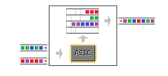
Why not? Because a switch forwards frames with ASICs, not with the CPU. And that means queueing is done in hardware too. And because the hardware contains a fixed number of queues, configuration is not done with a policy-map, but commands to manipulate these queues directly.
There are both ingress and egress queues, but this article will only explain egress queues, as ingress queueing has little relevance on a 3560/3750 platform. Also, I will only talk about DSCP values and ignore CoS, as this platform can use DSCP end-to-end. This article’s intent is to get a basic understanding of QoS on this platform. For a more detailed approach, this document in the Cisco Support community has proven very useful for me.
Queues and thresholds
The number of egress queues can be checked on a per-port basis:
Switch#show interfaces FastEthernet 0/1 capabilities | include tx|rx
Flowcontrol: rx-(off,on,desired),tx-(none)
QoS scheduling: rx-(not configurable on per port basis),
. tx-(4q3t) (3t: Two configurable values and one fixed.)
Notice the ‘4q3t’ number: this means the port supports for queues, each with three thresholds. Although the value can be checked on a per-port basis, the 3560/3750 series uses one ASIC for all it’s ports, so the number of queues and thresholds is the same on all ports.
The four queues are hard-coded: no more, no less. A queue can be left unused, but no extra queues can be allocated. The thresholds are used for tail drops (the dropping of a frame when the queue is full) and allow to differentiate between traffic flows inside a queue.
An example: the third queue has thresholds at 80%, 90% and 100% (The third threshold is always 100% and can’t be changed). You put packets with DSCP value AF31, AF32 and AF33 in the third queue, but on different thresholds: AF31 on 3, AF32 on 2, AF33 on 1. The consequence is that packets with these DSCP values are put into the queue until the queue is 80% full (the first threshold). At that point, frames of DSCP AF33 are dropped, while the other two are still placed in the queue. If the queue reaches 90%, packets with AF32 are dropped as well, so the remaining 10% of the queue can only be filled with AF31-marked packets.
Each queue also has a buffer: the buffer size determines the amount packets a queue can hold. The allocation of these buffers can be checked:
Wolfberry#show mls qos queue-set 1
Queueset: 1
Queue : 1 2 3 4
———————————————-
buffers : 25 25 25 25
threshold1: 100 200 100 100
threshold2: 100 200 100 100
reserved : 50 50 50 50
maximum : 400 400 400 400

A little explanation: everything is percentages here. The ‘buffers’ line indicates how the buffers are allocated: by default 25% for each queue. The exact amount can’t be found in the data sheets and supposedly depends on the exact type of switch.
The ‘reserved’ line means how much of those buffers are actually guaranteed to the queue. By default 50% of 25%, so 12.5% of the buffer pool is actually reserved for one queue. The other 50% of the total buffer pool can be used for any of the four queues that needs it. If all queues are filled and need it, it ends up at 25-25-25-25 again.
The other three lines are relative to the reserved value. The default first threshold of 100% means traffic set in threshold 1 of queue 1 will be dropped as soon as the queue is filled to its reserved value, 50% of the 25% allocated of the pool. The second threshold in queue 2, default 200%, means the queue will fill up to its allocated value, 100% of the 25% of the buffer pool. The maximum is the implicit third threshold, and is the maximum amount of buffer space that queue can use.
These values can all be changed with ‘mls qos queue-set output’ command. For example, let’s allocate more buffers to the second queue, as the intention is to use this for TCP traffic later on. Also let’s change other parameters: the queue will receive 50% of the buffer pool, 60% of this allocation will be reserved, and thresholds will be at 60% (100% of the reserved value), 90% (150% of the reserved value) and 120% (200% of the reserved value). Queue 1 receives 26% of the buffer pool, queue 3 & 4 each 12%. The thresholds for queue 1 will also change to 80% (160% of the reserved value) and 90% (180% of the reserved value) and 100% (200% of the reserved value).
Switch(config)#mls qos queue-set output 1 buffers 26 50 12 12
Switch(config)#mls qos queue-set output 1 threshold 2 100 150 60 200
Switch(config)#mls qos queue-set output 1 threshold 1 160 180 50 200
Switch(config)#exit
Switch#show mls qos queue-set 1
Queueset: 1
Queue : 1 2 3 4
———————————————-
buffers : 26 50 12 12
threshold1: 160 100 100 100
threshold2: 180 150 100 100
reserved : 50 60 50 50
maximum : 200 200 400 400

Queue mappings
Now that the queues have been properly defined, how do you put packets in them? Well, assuming you’ve marked them as explained in part III, all packets have a DSCP marking. The switch automatically put packets with a certain marking into a certain queue according to the DSCP-to-output-queue table:
Switch#show mls qos maps dscp-output-q
Dscp-outputq-threshold map:
d1 :d2 0 1 2 3 4 5 6 7 8 9
————————————————————
0 : 02-01 02-01 02-01 02-01 02-01 02-01 02-01 02-01 02-01 02-01
1 : 02-01 02-01 02-01 02-01 02-01 02-01 03-01 03-01 03-01 03-01
2 : 03-01 03-01 03-01 03-01 03-01 03-01 03-01 03-01 03-01 03-01
3 : 03-01 03-01 04-01 04-01 04-01 04-01 04-01 04-01 04-01 04-01
4 : 01-01 01-01 01-01 01-01 01-01 01-01 01-01 01-01 04-01 04-01
5 : 04-01 04-01 04-01 04-01 04-01 04-01 04-01 04-01 04-01 04-01
6 : 04-01 04-01 04-01 04-01
Again an explanation: this table explains which DSCP value maps to which queue and threshold. For example, DSCP 0 (first row, first column) maps to queue 2, threshold 1 (02-01). DSCP 46 (fourth row, sixth column) maps to queue 1, threshold 1 (01-01). To map DSCP values to a certain queue and threshold, use the ‘mls qos srr-queue output dscp-map’ command:
Switch(config)#mls qos srr-queue output dscp-map queue 2 threshold 2 34
This will map packets with DSCP value 34 to queue 2, threshold 2, for example.
Bandwidth sharing and shaping
So queues are properly configured, packets are correctly put into the queues according to DSCP values… Just one more thing: what do the queues do? This is where the Shaped Round Robin mechanism comes into play. It’s one of the few egress QoS configurations that is done on a per-port basis on the 3560/3750 platform. There are two commands: ‘srr-queue bandwidth shape’ and ‘srr-queue bandwidth share’, followed by four values for the four queues.
The ‘shape’ command polices: it gives bandwidth to a queue, but at the same time limits that queue to that bandwidth. Ironically it’s an inverted scale: 25, for example, means 1 in 25 packets, or 4%. 5 means 1 in 5 packets, or 20% bandwidth. If a zero is used, that queue is not shaped. The ‘share’ command does not limit bandwidth and gives it in a relative scale: if the total of the queues is 20 and queue 1 has value 5, that’s 25% bandwidth. If the total is 50 and queue 1 has value 5, that’s 10% bandwidth.
Switch(config-if)#srr-queue bandwidth share 10 150 30 20
Switch(config-if)#srr-queue bandwidth shape 20 0 0 0
The above gives 5% bandwidth to the first queue (one in 20 packets). The other three queues receive 75%, 15% and 10% bandwidth respectively. 150+30+20 is 200 (10 is not counted here, because this queue is already shaped). 150 of 200 is 75%, 30 of 200 is 15%, 20 of 200 is 10%. How the shaped and shared queues are counted together is not clear, after all, 105% of bandwidth is allocated now. But it would require all queues to be filled at the same time to reach this situation.
Low latency queuing
And finally, the 3560/3750 allows for one priority egress queue. If a packet is placed in this queue, it will be sent out next, regardless of what is in the other queues, until it reaches the maximum allowed bandwidth. This makes it ideal for voice and other low-latency traffic. By design, the priority queue has to be the first queue, so the command doesn’t have a number in it:
Switch(config-if)#priority-queue out
Sounds logical, right? You’re correct: absolutely not. Unfortunately, Cisco uses a different type of value system for each QoS command, and the only way getting a feeling for it is trying it out. I hope this does help understand the workings of QoS in hardware. In the next article, we’ll review another platform.

great articule