Tag Archive: BGP


This article further continues on earlier experiments. While using internal tunnels gave a logically ‘simple’ point-to-point network seen from a layer 3 point of view, it came with the drawback of complex header calculations, resulting in CPU hogging on devices capable of hardware switching. Using some route-maps to choose VRFs for flows proved interesting, but only in particular use cases. It didn’t make the troubleshooting any easier.

There is a better method for dealing with inter-VRF routing on a local device, but it requires a very different logic. Up until now, my articles described how to be able to select a next-hop inside another VRF. Route leaking using BGP, however, leverages a features of BGP that has been described in my blog before: the import and export of routing information in different VRFs.

How does it work? Well, since the BGP process can’t differentiate between VRFs based on names, but instead uses route-targets to uniquely identify routing tables, it’s the route target that matters. Usually, for MPLS-VPN, these numbers differ per VRF. This time, use the same number for two VRFs:

VRF-RouteLeaking1This will tell BGP later on to use the same routing table for both VRFs. Now if you configure BGP…

VRF-RouteLeaking2

… There’s still a separate configuration per VRF. How does the exchange happen? Well: for all routes that are known inside the BGP process. This means any routes from any BGP peer in one of the VRFs are automatically learned in both VRFs. But for static and connected routes, and routes from other routing protocols, you can do a controlled redistribution using route-maps or prefix lists. This way only the routes that need to be known in the other VRF are added.

VRF-RouteLeaking3

The routing table with automatically show routes pointing to different VRFs. On top of that, the forwarding does not require any headers to be added or removed to the packets, so it can be put directly into CEF, allowing for hardware forwarding. And for completeness: the BGP neighborships here are just for illustration of what happens, but no neighborship is required for this to function. BGP just needs to run on the device as a process.

Of course, this is just a simple setup. More complexity can always be added, as you can even use route-maps to set the route targets for some routes.

This article is not really written with knowledge usable for a production network in mind. It’s more of an “I have not failed. I’ve just found 10,000 ways that won’t work.” kind of article.

I’m currently in a mailing group with fellow network engineers who are setting up GRE tunnels to each others home networks over the public internet. Over those networks we speak (external) BGP towards each other and each engineer announces his own private address range. With around 10 engineers so far and a partial mesh of tunnels, it gives a useful topology to troubleshoot and experiment with. Just like the real internet, you don’t know what happens day-to-day, neighborships may go down or suddenly new ones are added, and other next-hops may become more interesting for some routes suddenly.

SwitchRouting1

But of course it requires a device at home capable of both GRE and BGP. A Cisco router will do, as will Linux with Quagga and many other industrial routers. But the only device I currently have running 24/7 is my WS-C3560-8PC switch. Although it has an IP Services IOS, is already routing and can do GRE and BGP, it doesn’t do NAT. Easy enough: allow GRE through on the router that does the NAT in the home network. Turns out the old DD-WRT version I have on my current router doesn’t support it. Sure I can replace it but it would cost me a new router and it would not be a challenge.

SwitchRouting2

Solution: give the switch a direct public IP address and do the tunnels from there. After all, the internal IP addresses are encapsulated in GRE for transport so NAT is required for them. Since the switch already has a default route towards the router, set up host routes (a /32) per remote GRE endpoint. However, this still introduces asymmetric routing: the provider subnet is a connected subnet for the switch, so incoming traffic will go through the router and outgoing directly from the switch to the internet without NAT. Of course that will not work.

SwitchRouting3

So yet another problem to work around. This can be solved for a large part using Policy-Based Routing (PBR): on the client VLAN interface, redirect all traffic not meant for a private range towards the router. But again, this has complications: the routing table does not reflect the actual routing being done, more administrative overhead, and all packets originated from the local switch will still follow the default (the 3560 switch does not support PBR for locally generated packets).

Next idea: it would be nice to have an extra device that can do GRE and BGP directly towards the internet and my switch can route private range packets towards it. But the constraint is no new device. So that brings me to VRFs: split the current 3560 switch in two: one routing table for the internal routing (vrf MAIN), one for the GRE tunnels (vrf BGP). However, to connect the two VRFs on the same physical device I would need to loop a cable from one switchport to another, and I only have 8 ports. The rest would work out fine: point private ranges from a VLAN interface in one VRF to a next-hop VLAN interface over that cable in another VRF. That second VRF can have a default route towards the internet and set up GRE tunnels. The two VRFs would share one subnet.

SwitchRouting4

Since I don’t want to deal with that extra cable, would it be possible to route between VRFs internally? I’ve tried similar actions before, but those required a route-map and a physical incoming interface. I might as well use PBR if I go that way. Internal interfaces for routing between VRFs exist on ASR series, but not my simple 8-port 3560. But what if I replace the cable with tunnel interfaces? Is it possible to put both endpoints in different VRFs? Yes, the 15.0(2) IOS supports it!

SwitchRouting5

The tunnel interfaces have two commands that are useful for this:

  • vrf definition : just like on any other layer 3 interface, it specifies the routing table of the packets in the interface (in the tunnel).
  • tunnel vrf :  specifies the underlying VRF from which the packets will be sent, after GRE encapsulation.

With these two commands, it’s possible to have tunnels in one VRF transporting packets for another VRF. The concept is vaguely similar to MPLS-VPN,  where your intermediate (provider) routers only have one routing table which is used to transport packets towards routers that have the VRF-awareness (provider-edge).

interface Vlan2
ip address 192.168.2.1 255.255.255.0
interface Vlan3
ip address 192.168.3.1 255.255.255.0
interface Tunnel75
vrf forwarding MAIN
ip address 192.168.7.5 255.255.255.252
tunnel source Vlan2
tunnel destination 192.168.3.1
interface Tunnel76
vrf forwarding BGP
ip address 192.168.7.6 255.255.255.252
tunnel source Vlan3
tunnel destination 192.168.2.1

So I configure two tunnel interfaces, both in the main routing table. Source and destination are two IP addresses locally configured on the router.  I chose VLAN interface, loopbacks will likely work as well. Inside the tunnels, one is set to the first VRF, the other to the second. One of the VRFs may be shared with the main (outside tunnels) routing table, but it’s not a requirement. Configure both tunnel interfaces as two sides of a point-to-point connection and they come up. Ping works, and even MTU 1500 works over the tunnels, despite the show interface command showing an MTU of only 1476!

Next, I set up BGP to be VRF-aware. Logically, there are two ‘routers’, one of which is the endpoint for the GRE tunnels, and another one which connects to it behind it for internal routing. Normally if it were two physical routers, I would set up internal BGP between them since I’m already using that protocol. But there’s no difference here: you can make the VRFs speak BGP to each other using one single configuration.

router bgp 65000
address-family ipv4 vrf MAIN
neighbor 192.168.7.6 remote-as 65000
network 192.168.0.0 mask 255.255.248.0
neighbor 192.168.7.6 activate
exit-address-family
address-family ipv4 vrf BGP
bgp router-id 192.168.7.6
neighbor 192.168.7.5 remote-as 65000
neighbor 192.168.7.5 activate
exit-address-family

A few points did surface: you need to specify the neighbors (the IP addresses of the local device in the different VRFs) under the correct address families. You also need to specify a route distinguisher under the VRF as it is required for VRF-aware BGP. And maybe the most ironic: you need a bgp router-id set inside the VRF address-family so it differs from the other VRF (the highest interface IP address by default), otherwise the two ‘BGP peers’ will notice the duplicate router-id and it will not work. But after all of that, BGP comes up and routes are exchanged between the two VRFs! For the GRE tunnels towards the internet, the tunnel vrf command is required in the GRE tunnels so they use the correct routing table for routing over the internet.

So what makes this not production-worthy? The software-switching.

The ASIC can only do a set number of actions in a certain sequence without punting towards the switch CPU. Doing a layer 2 CAM table lookup or a layer 3 RIB lookup is one thing. But receiving a packet, have the RIB pointing it to a GRE tunnel, encapsulate, decapsulate and RIB lookup of another VRF is too much. It follows the expected steps in the code accordingly, the IOS software does not ‘see’ what the point is and does not take shortcuts. GRE headers are actually calculated for each packet traversing the ‘internal tunnel’ link. I’ve done a stress test and the CPU would max out at 100% at… 700 kBps, about 5,6 Mbps. So while this is a very interesting configuration and it gives an ideal situation to learn more, it’s just lab stuff.

So that’s the lesson, as stated in the beginning: how not to do it. Can you route between VRFs internally on a Cisco switch or router (not including ASR series)? Yes. Would you want to do it? No!

Advantages of MPLS: an example.

While MPLS is already explained on this blog, I often still get questions regarding the advantages over normal routing. A clear example I’ve also already discussed, but besides VRF awareness and routing of overlapping IP ranges, there’s also the advantage of reduced resources required (and thus scalability).

WANEdgeDesign

Given the above design: two routers connecting towards ISPs using eBGP sessions. These in turn connect to two enterprise routers, and those two enterprise routers connect towards two backend routers closer to (or in) the network core. All routers run a dynamic routing protocol (e.g. OSPF) and see each other and their loopbacks. However, the two middle routers in the design don’t have the resources to run a full BGP table so the WAN edge routers have iBGP sessions with the backend routers near the network core.

If you configure this as described and don’t add any additional configuration, this design will not work. The iBGP sessions will come up and exchange routes, but those routes will list the WAN edge router as the next hop. Since this next hop is not on a directly connected subnet to the backend routers, the received routes will not be installed in the routing table. The enterprise routers would not have any idea what to do with the packets anyway.

Update January 17th, 2014: the real reason a route will not be installed in the routing table is the iBGP synchronisation feature, which requires the IGP to have learned the BGP routes through redistribution before using the route. Still, synchronisation can be turned off and the two enterprise routers would drop the packets they receive.

There are a few workarounds to make this work:

  • Just propagating a default route of course, but since the WAN edge routers are not directly connected to each other and do not have an iBGP session, this makes the eBGP sessions useless. Some flows will go through one router, some through the other. This is not related to the best AS path, but to the internal (OSPF) routing.
  • Tunneling over the middle enterprise routers, e.g. GRE tunnels from the WAN edge routers towards the backend routers. Will work but requires multiple tunnels with little scalability and more complex troubleshooting.
  • Replacing the middle enterprise routers by switches so it becomes layer 2 and the WAN edge and backend routers have a directly connected subnet. Again this will work but requires design changes and introduces an extra level of troubleshooting (spanning tree).

So what if MPLS is added to the mix? By adding MPLS to these 6 routers (‘mpls ip’ on the interfaces and you’re set), LDP sessions will form… After which the backend routers will install all BGP routes in their routing tables!

The reason? LDP will advertise a label for each prefix in the internal network (check with ‘show mpls ldp bindings’) and a label will be learned for the interfaces (loopback) of the WAN edge routers… After which the backend routers know they just have to send the packets towards the enterprise routers with the corresponding MPLS label.

And the enterprise routers? They have MPLS enabled on all interfaces and no longer use the routing table or FIB (Forwarding Information Base) for forwarding, but the LFIB (Label Forwarding Information Base). Since all packets received from the backend routers have a label which corresponds to the loopback of one of the WAN edge routers, they will forward the packet based on the label.

Result: the middle enterprise routers do not need to learn any external routes. This design is scalable and flexible, just adding a new router and configuring OSPF and MPLS will make it work. Since a full BGP table these days is well over 450,000 routes, the enterprise routers do not need to check a huge routing table for each packet which decreases resource usage (memory, CPU) and decreases latency and jitter.

Setting up a routing protocol neighborship isn’t hard. In fact, it’s so easy I’ve made them by accident! How? There were already two OSPF neighbors in a subnet and I was configuring a third router for OSPF with yet another fourth router. But because the third router had an interface in that same subnet and I used the command ‘network 0.0.0.0 255.255.255.255 area 0’ the neighborships came up. This serves as an example that securing a neighborship is not only to avoid malicious intent, but also to minimize human error.

Session authentication
The most straightforward way to secure a neighborship is adding a password to the session. However, this is not as perfect as it should be: it doesn’t encrypt the session so everyone can still read it, and the hash used is usually done in md5, which can easily be broken at the time of writing. Nevertheless, a quick overview of the password protection for EIGRP, OSPF and BGP:

Router(config)#key chain KEY-EIGRP
Router(config-keychain)#key 1
Router(config-keychain-key)#key string
Router(config-keychain-key)#exit
Router(config-keychain)#exit
Router(config)#interface Fa0/0
Router(config-if)#ip authentication mode eigrp 65000 md5
Router(config-if)#ip authentication key-chain eigrp 65000 KEY-EIGRP
Router(config-if)#exit

Router(config)#interface Fa0/1
Router(config-if)#ip ospf message-digest-key 1 md5
Router(config-if)#exit
Router(config)#router ospf 1
Router(config-router)#area 0 authentication message-digest
Router(config-router)#exit

Router(config)#router bgp 65000
Router(config-router)#neighbor 10.10.10.10 remote-as 65000
Router(config-router)#neighbor 10.10.10.10 password

Note a few differences. EIGRP uses a key chain. The positive side about this is that multiple keys can be used, each with his own lifetime. The downside: administrative overhead and unless the keys change every 10 minutes it’s not of much use. I doubt anyone uses this in a production network.

BGP does the configuration for a neighbor (or a peer-group of multiple peers at the same time for scalability). Although there’s no mention of hashing, it still uses md5. It works with eBGP as well but you’ll need to agree on this with the service provider.

OSPF sets the authentication key on the interface and can activate authentication on the interface, but here it’s shown in the routing process, as it’s likely you’ll want it on all interfaces. It would have been even better if it was possible to configure the key under the routing process, saving some commands and possible misconfigurations on the interfaces. OSPF authentication commands can be confusing, as Jeremy points out. However:

OSPFv3 authentication using IPsec
The new OSPF version allows for more. Now before you decide that you’re not using this because you don’t run IPv6, let it be clear that OSPFv3 can be used for IPv4 as well. OSPFv3 does run on top of IPv6, but only link-local addresses. This means that you need IPv6 enabled on the interfaces, but you don’t need IPv6 routing and there’s no need to think about an IPv6 addressing scheme.

Router(config)#router ospfv3 1
Router(config-router)#address-family ipv4 unicast
Router(config-router-af)#area 0 authentication ipsec spi 256 sha1 8a3fe4a551b81dc24f6148b03e865b803fec49f7
Router(config-router-af)#exit
Router(config-router)#exit
Router(config)#interface Fa0/0
Router(config-if)#ipv6 enable
Router(config-if)#ospfv3 1 area 0 ipv4
Router(config-if)#ospfv3 bfd

This new OSPF version shows two advantages: you can configure authentication per area instead of per interface, and you can use SHA1 for hashing. The key has to be a 40-digit hex string, it will not accept anything else. A non-hex character or 39 or 41 digits gives a confusing ‘command not recognized’ error. The SPI vaue needs to be the same on both sides, just like the key of course. The final command is to show optional BFD support.

EIGRP static neighbors
For EIGRP you can define the neighbors on the router locally, instead of discovering them using multicast. This way, the router will not allow any neighborships from untrusted routers.

Router(config)#router eigrp 65000
Router(config-router)#network 10.0.0.0 0.0.0.255
Router(config-router)#neighbor 10.0.0.2 Fa0/0
Router(config-router)#exit

Static neighbor definition is one command, but there is a consequence: EIGRP will stop multicasting hello packets on he interface where the static neighbor is. This is expected behavior, but easily forgotten when setting it up. Also, the routing process still needs the ‘network’ command to include that interface, or nothing will happen.

BGP Secure TTL
Small yet useful: checking TTL for eBGP packets. By default an eBGP session uses a TTL of 1. By issuing the ‘neighbor ebgp-multihop ‘ you can change this value. The problem is that an attacker can send SYN packets towards a BGP router with a spoofed source of a BGP peer. This will force the BGP router to respond to the session request (SYN) with a half-open session (SYN-ACK). Many half-open sessions can overwelm the BGP process and bring it down entirely.

TTL-Security

Secure TTL solves this by changing the way TTL is checked: instead of setting it to the hop count where the eBGP peer expects a TTL of 1, the TTL is set to 255 to begin with, and the peer checks upon arrival of the packet if the TTL is 255 minus the number of hops. Result: an attacker can send spoofed SYN packets, but since he’ll be more hops away and the TTL can’t be set higher than 255, the packets will arrive with a too low TTL value and are dropped without any notification. The configuration needs to be done on both sides:

Router(config)#router bgp 1234
Router(config-router)#neighbor 2.3.4.5 remote-as 2345
Router(config-router)#neighbor 2.3.4.5 ttl-security hops

These simple measures can help defend against the unexpected, and although it’s difficult in reality to implement them in a live network, it’s good to know when (re)designing.

Another series of articles. So far in my blog, I’ve concentrated on how to get routed networks running with basic configuration. But at some point, you may want to refine the configuration to provide better security, better failover, less chance for unexpected issues, and if possible make things less CPU and memory intensive as well.

While I was recently designing and implementing a MPLS network, it got clear that using defaults everywhere wasn’t the best way to proceed. As visible in the MPLS-VPN article, several different protocols are used: BGP, OSPF and LDP. Each of these establishes a neighborship with the next-hop, all using different hello timers to detect issues: 60 seconds for BGP, 10 seconds for OSPF and 5 seconds for LDP.

First thing that comes to mind is synchronizing these timers, e.g. setting them all to 5 seconds and a 15 second dead-time. While this does improve failover, there’s three keepalives going over the link to check if the link works, and still several seconds of failover. It would be better to bind all these protocols to one common keepalive. UDLD comes to mind, but that’s to check fibers if they work in both directions, it needs seconds to detect a link failure, and only works between two adjacent layer 2 interfaces. The ideal solution would check layer 3 connectivity between two routing protocol neighbors, regardless of switched path in between. This would be useful for WAN links, where fiber signal (the laser) tends to stay active even if there’s a failure in the provider network.

BFD-Session

Turns out this is possible: Bidirectional Forwarding Detection (BFD) can do this. BFD is an open-vendor protocol (RFC 5880) that establishes a session between two layer 3 devices and periodically sends hello packets or keepalives. If the packets are no longer received, the connection is considered down. Configuration is fairly straightforward:

Router(config-if)#bfd interval 50 min_rx 50 multiplier 3

The values used above are all minimum values. The first 50 for ‘interval’ is how much time in milliseconds there is between hello packets. The ‘mix_rx’ is the expected receive rate for hello packets. Documentation isn’t clear on this and I was unable to see a difference in reaction in my tests if this parameter was changed. The ‘multiplier’ value is how many hello packets kan be missed before flagging the connection as down. The above configuration will trigger a connection issue after 150 ms. The configuration needs to be applied on the remote interface as well, but that will not yet activate BFD. It needs to be attached to a routing process on both sides before it starts to function. It will take neighbors from those routing processes to communicate with. Below I’m listing the commands for OSPF, EIGRP and BGP:

Router(config)#router ospf 1
Router(config-router)#bfd all-interfaces
Router(config-router)#exit
Router(config)#router eigrp 65000
Router(config-router)#bfd all-interfaces
Router(config-router)#exit
Router(config)#router bgp 65000
Router(config-router)#neighbor fall-over bfd
Router(config-router)#exit

This makes the routing protocols much more responsive to link failures. For MPLS, the LDP session cannot be coupled with BFD on a Cisco device, but on a Juniper it’s possible. This is not mandatory as the no frames will be sent on the link anymore as soon as the routing protocol neighborships break and the routing table (well, the FIB) is updated.

Result: fast failover, relying on a dedicated protocol rather than some out-of-date default timers:

Router#show bfd neighbor

NeighAddr                         LD/RD    RH/RS     State     Int
10.10.10.1                       1/1     Up        Up        Fa0/1

Jun 29 14:16:21.148: %OSPF-5-ADJCHG: Process 1, Nbr 10.10.10.1 on FastEthernet0/1 from FULL to DOWN, Neighbor Down: BFD node down

Not bad for a WAN line.

MPLS, part II: VRF-aware MPLS-VPN.

Where MPLS part I explains the basics of labeling packets, it’s not giving any advantage over normal routing, apart from faster table lookups. But extensions to MPLS allow for more. In this article I’ll explain MPLS-VPN, and more specifically a Virtual Private Routed Network (VPRN).

A VPRN is a routed (layer 3) network over an MPLS cloud, that is VRF-aware, or customer-aware. This means several different routing instances (VRFs, remember?) can share the same MPLS cloud. How is this achieved when there’s only a point-to-point link between routers with one IP address? After all, an interface can only be assigned to one VRF. Solution: by adding a second MPLS label to the data: the ‘outer’ label (the one closest to the layer 2 header) is used to specify the destination router, the ‘inner’ label (closest to the original layer 3 header) is used to specify to which VRF a packet belongs. The outer label workings are identical to standard MPLS: these are learned by LDP and matched with a prefix in the routing table. But for the inner label, a VRF-aware process needs to run on each router that can handle label information and propagate it to other routers. That process is Multiprotocol-BGP, or MP-BGP.

MPLS-VPN-Header

The outer label is used to route the packet through the MPLS cloud, and the last router(s) use the inner label to see to which VRF a packet belongs. Let’s look at the configuration to understand it more. First, the basic setup:

MPLS-VPN-VRF

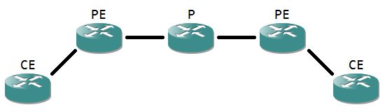
Notice the router names, as these are often used in MPLS terminology.

  • The Customer Edge router a router that directly connects to a customer network. It’s usually the demarcation point, where the equipment governed by the MPLS provider begins. Contrary to the name, the CE itself is often managed by the provider as well.
  • The Provider Edge router is the ‘first’ router (seen from a customer site point of view) that has MPLS enabled interfaces. It’s where the labels are applied for the first time.
  • A Provider router is a router completely internal to the MPLS cloud, having only MPLS enabled interfaces.

The connection between CE and PE is a point-to-point so a /30 subnet is logical. Routing between CE and PE is done using a simple routing protocol, like RIP, OSPF, EIGRP or even static or standard BGP. The only notable part is that the PE router has to use a VRF to place the customer in. Below an example configuration:

Router-CE(config)#interface G0/1
Router-CE(config-if)#ip address 10.1.0.1 255.255.255.252
Router-CE(config-if)#exit
Router-CE(config)#router ospf 1
Router-CE(config-router)#network 10.1.0.0 0.0.0.3 area 0

Router-PE(config)#vrf definition VRF
Router-PE(config-vrf)#address-family ipv4
Router-PE(config-vrf-af)#exit
Router-PE(config-vrf)#exit
Router-PE(config)#interface G0/1
Router-PE(config-if)#vrf forwarding VRF
Router-PE(config-if)#ip address 10.1.0.2 255.255.255.252
Router-PE(config-if)#exit
Router-PE(config)#router ospf 2 vrf VRF
Router-PE(config-router)#network 10.1.0.0 0.0.0.3 area 0
*Mar  1 00:06:20.991: %OSPF-5-ADJCHG: Process 2, Nbr 10.1.0.1 on GigabitEthernet0/1 from LOADING to FULL, Loading Done

If you happen to run a router on an IOS before 15.0, the commands for the VRF change: it becomes ‘ip vrf VRF’ to define a VRF, without the need to specify an address family, as 12.x IOS versions aren’t VRF aware for IPv6. On the interface, the command is ‘ip vrf forwarding VRF’.

So far so good. Now on to activating MPLS between the PE and the P router, and making sure the routers learn the MPLS topology:

Router-PE(config)#interface G0/2
Router-PE(config-if)#mpls ip
Router-PE(config-if)#ip address 10.0.0.1 255.255.255.252
Router-PE(config-if)#ip ospf network point-to-point
Router-PE(config-if)#exit
Router-PE(config)#interface Loopback0
Router-PE(config-if)#ip address 10.0.1.1
Router-PE(config-if)#exit
Router-PE(config)#router ospf 1
Router-PE(config-router)#network 10.0.0.0 0.0.1.255 area 0

Router-P(config)#interface G0/1
Router-P(config-if)#mpls ip
Router-P(config-if)#ip address 10.0.0.2 255.255.255.252
Router-P(config-if)#ip ospf network point-to-point
Router-P(config-if)#exit
Router-P(config)#interface Loopback0
Router-P(config-if)#ip address 10.0.1.2 255.255.255.255
Router-P(config-if)#exit
Router-P(config)#router ospf 1
Router-P(config-router)#network 10.0.0.0 0.0.1.255 area 0
*Mar  1 00:02:29.023: %OSPF-5-ADJCHG: Process 1, Nbr 10.0.0.1 on GigabitEthernet0/2 from LOADING to FULL, Loading Done
*Mar  1 00:02:33.127: %LDP-5-NBRCHG: LDP Neighbor 10.0.0.1:0 (1) is UP

The ‘ip ospf network point-to-point’ is not really needed but used to reduce OSPF overhead. The loopbacks are needed for BGP later on.

Up until this point, we have MPLS in the default VRF and a separate VRF per customer for routing, but no routing of the VRFs over the MPLS. To exchange the inner labels needed to specify the VRF, MP-BGP between PE and P is configured:

Router-PE(config)#router bgp 65000
Router-PE(config-router)#neighbor 10.0.1.2 remote-as 65000
Router-PE(config-router)#neighbor 10.0.1.2 update-source Loopback0
Router-PE(config-router)#no address-family ipv4
Router-PE(config-router)#address-family vpnv4
Router-PE(config-router-af)#neighbor 10.0.1.2 activate
Router-PE(config-router-af)#neighbor 10.0.1.2 send-community extended

Router-P(config)#router bgp 65000
Router-P(config-router)#neighbor 10.0.1.1 remote-as 65000
Router-P(config-router)#neighbor 10.0.1.1 update-source Loopback0
Router-P(config-router)#no address-family ipv4
Router-P(config-router)#address-family vpnv4
Router-P(config-router-af)#neighbor 10.0.1.1 activate
Router-P(config-router-af)#neighbor 10.0.1.1 send-community extended
*Mar  1 00:11:31.879: %BGP-5-ADJCHANGE: neighbor 10.0.1.1 Up

Again some explanation. First off, BGP neighbors always need to be defined under the main process, after which they need to be activated for a specific address-family. The ‘no address-family ipv4’ command means that no conventional routing information for the default VRF will be exchanged (we already have OSPF for that). The ‘address-family vpnv4’ activates the VPRN capability, and the label exchange for VRFs. In this process, the neighbor is activated. The ‘send-community extended’ means BGP will exchange the community Path Attributes (PA), in which the label information is present. The loopbacks are used to connect to each other, not only for redundancy in case a physical interface should go down, but also because LDP does not exchange labels with another router on a connected subnet for that subnet. This means that if the directly connected interfaces are used as BGP neighbors, the BGP process can’t figure out the labeling properly.

So VRF-aware MPLS is running now, but on each PE router it needs to be specified which VRF needs to be injected in the MPLS cloud. MP-BGP does this using import and export of routing tables. For MP-BGP, a route needs to be uniquely identified, and explained to which VRF it belongs. This is done with a Route Distinguisher (RD) and Route Target (RT). Both are 64 bits, and usually in the format AS:nn, or the first 32 bits the AS number and the last 32 bits a unique chosen number.

  • RD uniquely identifies a route. Inside MP-BGP, a route is prepended with its RD, e.g. 65000:1:192.168.1.0/24. This way, if the route exists twice (in different VRFs), it’s still unique because the RD part of the prefix is different.
  • RT specifies to which VRF a route belongs. It handles the import and export of routes from a VRF to the BGP process. In its basic form, it’s the same number as the RD, and the same at all PE routers for a certain client.

Configuration of these parameters is done inside the VRF:

Router-PE(config)#vrf definition VRF
Router-PE(config-vrf)#rd 65000:1
Router-PE(config-vrf)#route-target both 65000:1

Now that the VRF can be used in the BGP process, it is imported in the process as following:

Router-PE(config)#router bgp 65000
Router-PE(config-router)#address-family ipv4 vrf VRF
Router-PE(config-router-af)#redistribute ospf 2

The redistribution, of course, needs to be mutual between OSPF and BGP, so a few more lines of configuration are needed to complete everything:

Router-PE(config)#router ospf 2 vrf VRF
Router-PE(config-router)#redistribute bgp 65000 subnets

MPLS-VPN-Forwarding

And now everything is completed: the PE router learns routes from the P router by OSPF, and redistributes it into BGP to propagate them over the MPLS cloud. From this point on, configuration is modular: on another PE router, the configuration is likewise. Adding a P router isn’t any different from the P router in this example, the processes and parameters are the same each time. Do remember that routers don’t advertise iBGP-learned routes to other iBGP peers, so the PE and P routers need to form a full mesh, unless you’re using route reflectors or confederations.

A little bit of everything.

Yes, a bit of everything, that’s what it has been lately. First, I’m upgrading my home lab switches with more recent IOS versions. The 3560 on my desk can now run EIGRP for IPv6. My 2970 gigabit switch will follow tomorrow, with a K9 IOS this time to make it accessible via SSH.

Second is that I’ve been fine tuning my knowledge of layer 2 security features, using my 3560 desk switch and a 3750 test switch as subjects. RA Guard works great, and so does DHCP Snooping. DHCP Snooping has revealed a third functionality to me, next to countering rogue DHCP servers and preventing DHCP flooding: it also detects when a MAC address that sends an INFORM cannot be present on that port according to the mac address-table. It will generate a ‘%DHCP_SNOOPING-5-DHCP_SNOOPING_MATCH_MAC_FAIL’ message and drop the frame. Seems to be a functionality related to ARP Inspection.
And ARP Inspection, on the other hand, requires some planning of your DHCP servers: if multiple are present and they all reply at the same time, the DHCP Snooping feature, on which ARP Inspection relies, sometimes picks the wrong packet to add to it’s binding table. The client device selects another packet of the ones it received to configure itself, and thus ARP Inspection thinks there’s spoofing going on. I’m still figuring out how to effectively counter that.

Third is that I’ve ordered the CCIE Routing and Switching Certification Guide, 4th Edition hardcover, so I have a lot of reading to be done soon. I have to admit that I don’t like to read ebooks on a big screen so far, and I’m reluctant to buy a reader.
Yesterday I also tried a MPLS lab for the first time, with BGP-MP in GNS3. It did take me several hours but I managed to get it running. Not bad for never having done anything MPLS related before. Still, it’s a huge topic and I’ll need to learn a lot more about that.

And last, I tested an Aruba Remote Access Point (RAP). I’ve already tested Instant Access Points. The RAP works different: once booted, it needs an internet connection. When connecting a computer (it has LAN interfaces, just like a consumer-grade router), it redirects to a setup page, where you have to enter the public IP address of a Wireless LAN Controller (WLC). It then tries to negotiate a tunnel through NAT-T over UDP port 4500 to that WLC. It works by encapsulating IPsec in a UDP header, bypassing any NAT devices that are incapable of keeping the NAT state of IPsec.
The RAP tries to authenticate itself at the WLC using his MAC address. After whitelisting it and configuring a wireless profile (which contains the list of SSIDs to send out), I had to reboot the RAP. I ended up rebooting it several times, thinking it didn’t work, but eventually it turned out my cable had broken due to all the times I plugged it in and out again. The RAP booted fine and started sending out the correct SSIDs. Initially, the wireless connection didn’t hand out an IP to me, but after five minutes, everything suddenly got an IP and started working as if there had never been a problem. Not sure why this happened, although I suspect my NAT router of dropping some of the UDP packets (which wouldn’t be the first time).

A little bit of everything indeed.

Knowledge gained this week.

The past weeks have been very informative for me and I learned a lot about many network-related things. As you may have noticed, I’ve been giving my attention to OpenBSD mostly, as I am determined to learn and control this system. It’s low cost allows for some home use.

More parts will follow, however, I’ve run into problems and my OpenBSD’s do not react as expected for the moment, and sometimes don’t react at all. I’m unsure what is causing it, but it appears to be related to the fact that I’m running all my OpenBSD’s in VMware Workstation 8. They don’t accept certain packets destined for them, even though they show up in tcpdump. I added firewall rules in pf and eventually even disabled pf entirely (the command: ‘pfctl -d’ for disabling and ‘pfctl -e’ for enabling), but it didn’t change anything.

I’ve also sold part of my home lab: two 2611’s and the 2900XL, as well as a console cable, a serial cable, and some Ethernet cables. Stuff I don’t really need anymore, but provide a decent CCNA lab to another motivated network engineer-to-be out there.

And finally, I’ve had the chance to do BGP troubleshooting, when it was discovered a local ISP didn’t provide routing for certain IP prefixes. A very important tool in this is a Looking Glass Server, which is a router that has an iBGP session with an ISP BGP router, on which you can query for the reachability of routes on the internet. Useful, even for single-homed connections, to see if there is an ISP problem. The Looking Glass I use are those of Level 3 Communications: http://lg.level3.net/.

That’s it for this week. For next week: either more OpenBSD, or wireless and EIGRP, depending on what works and what not. Greetings!

IPv6 routes with MP-BGP.

BGP is a typical CCNP/CCIP topic, as is IPv6. But a combination of the two is rarely mentioned. Yet, just as with IPv4, BGP is mandatory for internet access. For IPv6, MultiProtocol BGP or MP-BGP is used.

MP-BGP

In the above sample network, both routers are part of a different AS. They have loopbacks configured with a subnet that has to be advertised by BGP. The link between the two is also IPv6. To configure MP-BGP you’ll need a reasonably up to date IOS: I’m using a 12.4. The config of the left router:

R1(config)#ipv6 unicast-routing
R1(config)#int lo0
R1(config-if)#ipv6 address 2001:0:0:10::1/64
R1(config-if)#exit
R1(config)#int f0/0
R1(config-if)#ipv6 address 2001:0:1:1::1/64
R1(config-if)#no shut
R1(config-if)#exit
R1(config)#router bgp 65001
R1(config-router)#no bgp default ipv4-unicast
R1(config-router)#bgp router-id 1.1.1.1
R1(config-router)#neighbor 2001:0:1:1::2 remote-as 65002
R1(config-router)#address-family ipv6
R1(config-router-af)#neighbor 2001:0:1:1::2 activate
R1(config-router-af)#network 2001:0:0:10::/64
R1(config-router-af)#exit-address-family

Some details here. ‘ipv6 unicast-routing’ is obviously required to make IPv6 routing possible. The interfaces are configured with the appropriate addresses and BGP for AS 65001 is set up. ‘no bgp default ipv4-unicast’ is the first important command here: it changes BGP to support multiple protocols. ‘address-family ipv6’ is the second important command: it defines the IPv6 parameters. Just like with standard BGP, a ‘network’ command defines the network(s) to advertise. And just like standard BGP, the network has to be present in the local routing table or no advertisement will be made.

Note that I’m advertising a /64 subnet here. While this works, in practice most ISPs will not accept a prefix more specific than a /48. Also, for once the ‘exit’ command is different, though typing ‘exit’ will work just the same. Oh, and the ‘router-id’ command is because no IPv4 address has been defined, which normally determines the router-id.

The config of the right router:

R2(config)#ipv6 unicast-routing
R2(config)#int f0/0
R2(config-if)#ipv6 addr 2001:0:1:1::2/64
R2(config-if)#no shut
R2(config-if)#int lo0
R2(config-if)#ipv6 address 2001:0:0:20::1/64
R2(config-if)#exit
R2(config)#router bgp 65002
R2(config-router)#no bgp default ipv4-unicast
R2(config-router)#bgp router-id 2.2.2.2
R2(config-router)#address-family ipv6
R2(config-router-af)#neighbor 2001:0:1:1::1 activate
% Specify remote-as or peer-group commands first
R2(config-router-af)#neighbor 2001:0:1:1::1 remote-as 65001
R2(config-router-af)#neighbor 2001:0:1:1::1 activate
*Mar  1 00:09:49.171: %BGP-5-ADJCHANGE: neighbor 2001:0:1:1::1 Up
R2(config-router-af)#network 2001:0:0:20::/64
R2(config-router-af)#end

A similar configuration. This time I’ve set the ‘neighbor remote-as’ command inside the ‘address family ipv6’ context. This does not seem to matter, as long as it is defined before the activation command. Just like BGP, MP-BGP uses TCP port 179 for the connection, which you can see with the following command:

R2#show tcp brief
TCB       Local Address           Foreign Address        (state)
64F460B8  2001:0:1:1::2.179       2001:0:1:1::1.26321    ESTAB

It also show that the left router (R1) initiated the connection to R2 on port 179. The result is visible with ‘show ipv6 route’:

B   2001:0:0:10::/64 [20/0]
via FE80::C000:3FF:FEA4:0, FastEthernet0/0

MP-BGP works and networks are propagated.

Interestingly, the IOS allows you to define IPv4 MP-BGP peers for IPv6 networks, accepting all commands. It even tries to set up a TCP connection, but this connection times out, looping forever and never establishing completely. I’m not sure why this is, as I had expected the TCP session to form but no information being exchanged because of missing next-hop IPv6 addresses. It seems IOS is a bit buggy on this part.

I used this information on the Cisco website as part of this example.