Tag Archive: Switching


I know, it’s been quiet on this blog for the past months. But here we are again, starting off with a simple post. Maybe not much real world practical use, but fun to know.

Dealing with ACLs requires more protocol knowledge compared to dealing with a stateful firewall. A stateful firewall takes care of return traffic for you, and often even has some higher layer functionality so it can automatically allow the incoming port of a FTP connection, for example.

ACLs don’t do this. They’re static and don’t care for return traffic. On a switch in particular, they’re done on the ASIC, in hardware. This means there is no logging possible. On the plus side, the filtering doesn’t consume CPU. Many engineers assume stateful firewalls are superior to ACLs, and while this is certainly true concerning scalability and manageability, it’s not 100% true for security. ACLs don’t get fooled by some attacks: they’re not dynamic like the stateful filtering principle, so they will also not work for attacks that try to use the stateful functionality of a firewall against it. Attacks involving many packets attempting to use op CPU also don’t work. True, these attacks are not common, but it’s still a forgotten advantage.

Concerning logging, an ACL does have the option, even on a switch. By adding the ‘log’ parameter to the end of a line you can count the hits on the ACL. However, all this does on the ASIC is punt the packet towards the CPU, who then processes the packet in software and increases a counter and logs a syslog message. If you do this for a lot of packets, or all of them, you’re essentially using the CPU for switching. This defeats the purpose of the ASIC. Most Cisco switch don’t have the CPU for that, limiting throughput and causing high CPU, latency, jitter, even packetloss.

But there’s a more efficient way to do this, for TCP at least: only log the connection initiations.

permit tcp any any established
permit tcp any any eq 80
permit tcp any any eq 443
permit tcp any any eq 22 log
permit udp any any
deny ip any any

In the above ACL the first line will allow all TCP traffic for which there already is a connection established. Just this rule doesn’t allow any traffic: you still need to be able to initiate traffic too. The two rules below it allow HTTP and HTTPS. Finally, the fourth rule allows SSH but also logs it. When a user creates an SSH session through the interface, the first SYN packet will match the log rule and the connection will be logged. All packets of the same flow after this will match the first rule and be switched in hardware. Minimal CPU strain, but connections are logged. Apart from the first packet the flow is forwarded in hardware.

This way of ACL building also has advantages on CPU-based platforms like (low-end) routers: most packets will hit the first line of the ACL and only a few packets will require multiple ACL entries to be checked by the CPU, decreasing general load.

Disclaimer: the logs are taken from a production network but the values (VLAN ID, names) are randomized.

Recently, I encountered an issue on a Campus LAN while performing routine checks: spanning tree seemed to undergo regular changes.

The LAN in question uses five VLANs and RPVST+, a Cisco-only LAN. At first sight there was no issue:

BPDU-Trace1

On an access switch, one Root port towards the Root bridge, a few Designated ports (note the P2P Edge) where end devices connect, and an Alternative port in blocking with a peer-to-peer neighborship, which means BPDUs are received on this link.

There is a command that allows you to see more detail: ‘show spanning-tree detail’. However, the output from this command is overwhelming so it’s best to apply filters on it. After some experimenting, filtering on the keywords ‘from’,’executing’ and ‘changes’ seems to give the desired output:

BPDU-Trace2

This gives a clear indication of something happening in the LAN: VLAN 302 has had a spanning-tree event less than 2 hours ago. Compared to most other VLANs who did not change for almost a year, this means something changed recently. After checking the interface on which the event happened, I found a port towards a desk which did not have the BPDU Guard enabled, just Root Guard. It was revealed that someone regularly plugged in a switch to have more ports, which talked spanning-tree but with a default priority, not claiming root. As such, Root Guard was not triggered, but the third-party switch did participate in spanning-tree from time to time.

Also, as you notice in the image, VLAN 304 seemed to have had a recent event to, on the Alternative Port. After logging in on the next switch I got the following output:

BPDU-Trace3

Good part: we have a next interface to track. Bad news: it’s a stack port? Since it’s a stack of 3750 series switches, it has stack ports in use, but the switches should act as one logical unit in regards to management and spanning-tree, right? Well, this is true, but each switch still makes the spanning-tree calculation by itself, which means that it can receive a spanning-tree update of another switch in the stack through the stack port.

Okay, but can you still trace this? You would have to be able to look in another switch in the stack… And as it turns out, you can:

BPDU-Trace4

After checking which stack port connects to which switch in the CLI, you can hop to the next one with the ‘session’ command and return to the master switch simply by typing ‘exit’. On the stack member, again doing the ‘show spanning tree detail’ command shows the local port on which the most recent event happened. And again the same thing: no BPDU Guard enabled here.


Just a simple article about something I recently did in my home network. I wanted to prepare the network for a Squid proxy, and design it in such a way that the client devices did not require proxy settings. Having trouble placing it inline, I decided I could use WCCP. However, that requires separate VLANs.

This did pose a problem: my home router did not support any kind of routing and multiple networks beyond a simple hide NAT (PAT) behind the public IP address. Even static routes weren’t possible.

And again my fanless 3560-8PC helped me out. The 3560 can do layer 3 so you can configure it with the proper VLANs and use it as the default gateway on all VLANs. Then you add another VLAN towards the router and point a default route towards that router.

That solves half of the problem: packets get to the router and out to the internet. However, the router does not have a return route for the VLANs. But it does not need that: you can use Proxy ARP. As the router will use a /24 subnet, you can subnet all VLANs inside that /24, e.g. a few /26 and a /30 for the VLAN towards the router, as my home network will not grow beyond a dozen devices in total. Now the router will send an ARP request for each inside IP address, after which the layer 3 switch answers on behalf of the client device. The router will forward all data to the layer 3 switch, who knows all devices in the connected subnets.

ProxyARP

And problem solved. From the point of view of the router, there’s one device (MAC address, the layer 3 switch) in the entire subnet that uses a bunch of IP addresses.

And no FabricPath either. This one works without any active protocol involved, and no blocked links. Too good to be true? Of course!

LAN-NoSTP

Take the above example design: three switches connected by port channels. Let’s assume users connect to these switches with desktops.

Using a normal design, spanning tree would be configured (MST, RPVST+, you pick) and one of the three port-channel links would go into blocking. The root switch would be the one connecting to the rest of the network or a WAN uplink, assuming you set bridge priorities right.

Easy enough. And it would work. Any user in a VLAN would be able to reach another user on another switch in the same VLAN. They would always have to pass through the root switch though, either by being connected to it, or because spanning tree blocks the direct link between the non-root switches.

Disabling spanning-tree would make all links active. And a loop would definitely follow. However, wouldn’t it be nice if a switch would not forward a frame received from another switch to other switches? This would require some sort of split horizon, which VMware vSwitches already do: if a frame enters from a pNIC (physical NIC) it will not be sent out another pNIC again, preventing the vSwitch from becoming a transit switch. Turns out this split horizon functionality exists on a Cisco switch: ‘switchport protect’ on the interface, which will prevent any frames from being sent out that came in through another port with the same command.

Configuring it on the port channels on all three switches without disabling spanning tree proves the point: the two non-root switches can’t reach each other anymore because the root switch does not forward frames between the port channels. But disabling spanning tree after it creates a working situation: all switches can reach each other directly! No loops are formed because no switch forwards between the port channels.

Result: a working network with active-active links and optimal bandwidth usage. So what are the caveats? Well…

  • It doesn’t scale: you need a full mesh between switches. Three inter-switch links for three switches, six for four switches, ten for five switches,… After a few extra switches, you’ll run out of ports just for the uplinks.
  • Any link failure breaks the network: if the link between two switches is broken, those two switches will not be able to reach each other anymore. This is why my example uses port-channels: as long as one link is active it will work. But there will not be any failover to a path with better bandwidth.

Again a disclaimer, I don’t recommend it in any production environment. And I’m sure someone will (or already has) ignore(d) this.

On this blog I’ve often covered Private VLANs: how to configure them, work around them and deploy them in a larger network. Yet it’s rarely that you see an actual Private VLAN in a design. Part of the problem is covered in the article about deployment over multiple switches: you can’t connect a trunked device such as a firewall to it. Although the Nexus 7000 provides a solution, that doesn’t make it much easier (or cheaper).

Another important reason is that few are willing to take the risk to deploy a VLAN where hosts cannot communicate with each other, as this is usually the reason hosts are put in the same VLAN in the first place. There’s the hesitation because it would introduce complexity or limit scalability, as new servers later on may need to communicate in the same subnet after all.

So where would it be beneficial and with low risk to use a Private VLAN? Actually quite a few places.

E-commerce
AppFlowDMZ

Say you have an internet-facing business with e-commerce websites where anyone can log in, create an account, or do a purchase. A compromised e-commerce server in the DMZ means immediate access to the entire DMZ VLAN. This VLAN has the highest chance of being compromised from the internet, yet the servers in it rarely need to speak with each other. In fact, if properly designed, they will all connect to backend application and/or database servers that on their turn communicate with each other. This way the e-commerce data is synchronised without the DMZ servers requiring a connection to each other.

Stepping Stones
SteppingStones

Some environments have a VLAN with Stepping Stone servers where users can log on to with pre-installed tools to access confidential resources. Access from one Stepping Stone server to another is not needed here. Sometimes it’s even not desired as there may be a Stepping Stone per application, environment or third-party.

Out-of-Band
A modern rackserver has an out-of-band port to a dedicated chip in the server that can power off and on the server, and even install the OS remotely. For example, HP iLO. Typical here is that the out-of-band port never initiates connections but only receives connections for management, usually though the default gateway. This makes for a good Private VLAN deployment without issues.

Backup
BackupVLAN

Similar to out-of-band, some environments use a dedicated network card on all servers for backup. This introduces a security issue as it’s possible for two servers in different VLANs to communicate without a firewall in between. Again a Private VLAN can counter this. Somewhat unusual in the design is that it’s best to put the servers taking the backup in the promiscuous VLAN, so they can communicate with all servers and the backup VLAN default gateway, and put the default gateway in an isolated VLAN, preventing any other server from using it.

Campus – Wired guests
Similar to the Stepping Stones: guests can access the network through a firewall (the default gateway) but don’t need to access each others computers.

Campus – Wireless APs
In a WLAN deployment with a central controller (WLC), all the Lightweight APs do is connect to the controller using the subnet default gateway. Any other services such as DHCP and DNS will be through this default gateway as well.

Campus – Utilities
Utilities such as printers, camera’s, badge readers,… will likely only need the default gateway and not each other.

Where not to use PVLANs
This should give some nice examples already. But for last, a couple of places where not to use Private VLANs:

  • Routing VLANs: unless you want to troubleshoot neighborships not coming up.
  • VLANs with any kind of cluster in it: still doable with community VLANs for the cluster synchronisation, but usually better off in their own VLAN.
  • User VLANs, VOIP VLANs and the like: VOIP and videoconferencing may set up point-to-point streams.
  • Database server VLANs: not really clusters but they will often require access to each other.

If you ever managed a Campus LAN, you’ll know what happens with a lot of end users that have access to ethernet cables on desks. The occasional rogue hub, a loop now and then, and if they have access to some more advanced tools, some BPDU’s and a rogue DHCP server. Most of these events are not intended to be malicious (even the BPDU’s and rogue DHCP), but they happen because end users are not aware of the impact of some devices on the network.

But, given a malicious intend, what are the possibilities of attacking a switched Cisco network from a directly attached interface? Operating system for all the upcoming attacks: BackTrack Linux, which has many interesting tools installed.

MAC Flood
The classic attack first: flooding the switch’s CAM table with random source MAC addresses.
Tool: macof
Countermeasure: port-security

First attacking without port security: as expected, CAM table fills, CPU increases and everything is flooded. Congestion everywhere.

L2Attack-1

Finding this attack without port-security is feasible by checking CPU processes: HLFM address learning doesn’t normally consume that much CPU. Turning of MAC address learning does the same but without CPU impact.

So does turning port-security on solve the problem? It depends. Turning it on and setting it to only block new mac addresses but not shutting down the port actually makes things worse for the CPU:

L2Attack-2

The best solution: port-security with shutdown of the port in case of too many MAC addresses. No flooding, no CPU hogging.

CDP Flood
A Cisco-only attack. Flooding CDP frames with fake neighbors, causing not only CPU spikes, but also clogging the memory with all the neighbor entries. ‘show cdp neighbor’ becomes like showing the route table on a BGP router: endless.
Tool: Yersinia
Countermeasure: disabling CDP on the port or globally.

The attack with CDP turned on (the default) is very effective:

L2Attack-3

Finding the attack is easy, as both CPU and memory will clearly show the CDP process is using up resources. However, without CDP on the port, the attack does nothing. So the best solution: always turn CDP off towards a user-facing port. Even behind an IP Phone, although some functionality will be lost.

Root BPDU inject
A funny one. Inject a BPDU claiming to be root to cause spanning-tree recalculations and creating suboptimal paths in the network.
Tool: Yersinia
Countermeasure: Root Guard.

L2Attack-4

Notice the root ID, which has a nearly identical MAC address to make it difficult to spot the difference, and the aging time of two days, making this an attack that will last while the attacker is no longer connected. Root Guard on the port counters this attack easily though.

BPDU Flood
This attack doesn’t try to change the spanning-tree topology, but rather overload the STP process. Consequence is high CPU and eventually spanning tree inconsistencies.
Tool: Yersinia
Countermeasure: BPDU Guard

L2Attack-5

Spanning-tree should not use that much CPU on a switch. HLFM address learning will increase too due to the random source MAC addresses, and depending on the switch, Hulc LED Process will increase too. This is the process that governs the LED status of all switchports: the more ports the switch, the more this process will consume CPU if flooding attacks are happening.

BPDU Guard stops this effectively by shutting down the port. BPDU Filter not so much: it still needs to look at the BPDU to drop it and not forward it in hardware. BPDU Filter is generally not recommended anyway.

DHCP Discover Flood
Not really a layer 2 attack, but still impacting for the local subnet. Sending a flood of DHCP Discover messages, quickly overloading the DHCP Server(s) for the subnet.
Tool: Yersinia
Countermeasure: DHCP Snooping and DHCP Snooping Rate Limit

If DHCP Snooping isn’t enabled on the switch, it behaves like a MAC Flood attack and can be countered accordingly. Simply enabling DHCP Snooping, which is against rogue servers and not against flooding, makes things worse.

L2Attack-6Not only does it make the CPU spike, but it’s one of the few attacks that makes the switch unresponsive in the data plane, meaning not only management is lost, but the switch stops forwarding most frames, with packet loss on all ports. Simple snooping does prevent execution from a virtual machine:

L2Attack-7

But to really protect against this attack, DHCP Snooping rate-limiting helps:

L2Attack-8

OSPF Flood
Sending a flood of OSPF Hello packets over a switch.
Tool: a virtual machine running ospfd (Vyatta, OpenBSD), and a hub between switch and computer with cable loop to cause the flood.
Countermeasure: ACL

For this one I didn’t use any specific tool. I just made my computer send out an OSPF Hello, and made sure the hub between computer and switch was wired so it would flood the frame. Result: spectacular. The switch CPU rises to 100% and management connections, including console, are dropped. Reason is that the OSPF process has higher priority. But now the shocking part: this was done on a layer 3 Cisco switch without OSPF configured, and without an IP address in the attacker VLAN.

Explanation: Cisco switches use something called pak_priority. It means that certain packets on ingress are labeled by the interface driver as priority and to be checked by CPU (Source). This is done to make sure network control packets get to the CPU in case of congestion. It’s the case for RIP, OSPF and EIGRP, but not for BGP packets.

I retried it with EIGRP (although this required a second Cisco device to generate the EIGRP hello) and the result is the same: no EIGRP configuration on the switch, still impact. The data plane does not have any impact: forwarding stays as usual mostly.

Solution? Strange enough, an ACL on each port blocking EIGRP (IP Protocol 88) and OSPF (IP Protocol 89) and allowing everything else seems to work. The ACL is checked in hardware as long as the ‘log’ parameter isn’t present. So for better security, it seems you’re stuck with an ACL on each switchport of a layer 3 switch.

Conclusion
I’m sure most of the readers now conclude that there’s still a security leak somewhere in their network. Just for reference, I’ll include the CPU graph of an hour of testing all these attacks.

L2Attack-9

On to a bigger platform: the 6500 series, Cisco’s flagship Campus LAN switch. Unlike the previously discussed platform, the 6500 series uses the older Weighted Round Robin (WRR) queueing mechanism, and uses CoS internally to put packets in queues.

Queues and thresholds
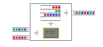
The capabilities per port also differ per line card and unlike the 3560/3750 series, it uses multiple ASIC per line card.

Switch#show interfaces GigabitEthernet 1/2/1 capabilities | include tx|rx|ASIC
Flowcontrol:                  rx-(off,on,desired),tx-(off,on,desired)
QOS scheduling:           rx-(1q8t), tx-(1p3q8t)
QOS queueing mode:    rx-(cos), tx-(cos)
Ports-in-ASIC (Sub-port ASIC) : 1-24 (1-12)

The above output is of a WS-X6748-GE-TX line card. The ‘1p3q8t’ for egress (tx) means one fixed priority queue and three normal queues, each with eight thresholds. The fixed priority queue cannot be changed to a normal queue: if a packet is in the queue, it will be transmitted next.

QoS9

The ingress ‘1q8t’ means there is one ingress queue with eight thresholds. Unlike the 3560/3750, there is some oversubscription on the line card. It has two ASICs, one per 24 ports (the line card is 48 ports total). Each of these ASICs has a 20 Gbps connection to the 6500 backplane. If all 24 gigabit ports together on that part of the line card start receiving more than 20 Gbps of traffic, the ASIC and backplane connection will not be able to handle all the traffic. Granted, this is a rare event: 24 Gbps maximum throughput on a 20 Gbps capable ASIC is an oversubscription of 1.2 to 1. But in case this happens, the different thresholds can help decide which traffic to drop. However, to drop on ingress, the decision must be made on existing markings.  The ASIC does classification and remarking, and the ingress queue is before the ASIC. This is not a problem usually, since classification and marking is best done at the access layer and 6500s are best used for distribution and core layer.

Switch#show interfaces TengigabitEthernet 1/9/1 capabilities | include tx|rx|ASIC
Flowcontrol:                  rx-(off,on),tx-(off,on)
QOS scheduling:           rx-(1p7q2t), tx-(1p7q4t)
QOS queueing mode:    rx-(cos,dscp), tx-(cos,dscp)
Ports-in-ASIC (Sub-port ASIC) : 1-8 (1-4)

The WS-X6716-10GE, a 10 GE line card, has different queues, especially for ingress. This line card has a high oversubscription of 4:1 and one ASIC per eight ports, for a total of two ASIC for the 16-port line card. This means that, while eight ports can deliver up to 80 Gbps, the ASIC and backplane connection behind it are still just 20 Gbps. The ASIC is much more likely to get saturated, so ingress queueing becomes important here. The fixed priority queue allows some traffic to be handled by the ASIC in low latency, even when saturated.

I’m only going to explain these two line cards, the rest is similar. A full list with details per line card can be found here. The logic is similar to the 3560/3750 platform: configure the buffers and the thresholds, but this time for both ingress and egress. First the ingress queue on the gigabit interface. The ingress queue has no buffer sizing command, as this line card has only one ingress queue.

Switch(config)#interface Gi1/2/1
Switch(config-if)#rcv-queue threshold 1 65 70 75 80 85 90 95 100
Warning: rcv thresholds will not be applied in hardware.
To modify rcv thresholds in hardware, all of the interfaces below
must be put into ‘trust cos’ state:
Gi1/2/1 Gi1/2/2 Gi1/2/3 Gi1/2/4 Gi1/2/5 Gi1/2/6 Gi1/2/7 Gi1/2/8 Gi1/2/9 Gi1/2/10 Gi1/2/11 Gi1/2/12
Switch(config-if)#

That configures the eight thresholds for the first and only queue: threshold 1 at 65%, threshold 2 at 70%, and so on. Note the warning: for ingress queueing, existing cos markings have to be trusted. Also, remember that the 3560/3750 ingress and buffer allocation commands work switch-wide, because it has one ASIC per switch. The X6748 line card on a 6500 has two ASIC, which for QoS are sub-divided in two sub-ASIC per twelve ports. Applying a command that changes the ASIC QoS allocations means that the command will automatically apply to the other twelve interfaces as well.

Next, egress queueing. First configuring buffer allocations, next the thresholds for the first queue, similar to the ingress queue.

Switch(config-if)#wrr-queue queue-limit 70 20 10
Switch(config-if)#wrr-queue threshold 1 65 70 75 80 85 90 95 100
Switch(config-if)#exit

Again something special here: the buffer allocation command ‘wrr-queue queue-limit’ needs only three values despite four queues. This is because queue 4, the priority queue, is a strict priority queue: any packet entering it will be serviced next. This means that if a lot of traffic ends up in the priority queue, it can end up clogging the other queues because these will not be serviced anymore. The only way to counter this is to tightly control what ends up in that queue.

On to the 10 GE line card. First ingress, this time with a buffer command because there are multiple queues on ingress.

Switch(config)#interface Te1/9/1
Switch(config-if)#rcv-queue queue-limit 40 20 20 0 0 0 20
Warning: rcv queue-limit will not be applied in hardware.
To modify rcv queue-limit in hardware, all of the interfaces below
must be put into ‘trust cos’ state:
Te1/9/1 Te1/9/2 Te1/9/3 Te1/9/4
Switch(config-if)#
Switch(config-if)#rcv-queue threshold 2 80 100
Switch(config-if)#rcv-queue threshold 3 90 100
HW-QOS: Rx high threshold 2 is fixed at 100 percent

Propagating threshold configuration to:  Te1/9/1 Te1/9/2 Te1/9/3 Te1/9/4
Warning: rcv thresholds will not be applied in hardware.
To modify rcv thresholds in hardware, all of the interfaces below
must be put into ‘trust cos’ state:
Te1/9/1 Te1/9/2 Te1/9/3 Te1/9/4
Switch(config-if)#end

The 10 GE line card has one ASIC per eight ports, one sub-ASIC for QoS per four ports. It has two thresholds per queue. The rest isn’t any different from previous configurations.

Queue mappings
As mentioned already, internally the 6500 platform uses CoS to determine in which queue a packet (and thus flow) ends up, although some newer line cards can work with both CoS and DSCP. The mappings are again similar to previous configurations:

Switch(config)#interface Gi1/2/1
Switch(config-if)#rcv-queue cos-map 1 4 5
Propagating cos-map configuration to:  Gi1/2/1 Gi1/2/2 Gi1/2/3 Gi1/2/4 Gi1/2/5 Gi1/2/6 Gi1/2/7 Gi1/2/8 Gi1/2/9 Gi1/2/10 Gi1/2/11 Gi1/2/12
Warning: rcv cosmap will not be applied in hardware.
To modify rcv cosmap in hardware, all of the interfaces below
must be put into ‘trust cos’ state:
Gi1/2/1 Gi1/2/2 Gi1/2/3 Gi1/2/4 Gi1/2/5 Gi1/2/6 Gi1/2/7 Gi1/2/8 Gi1/2/9 Gi1/2/10 Gi1/2/11 Gi1/2/12
Switch(config-if)#wrr-queue cos-map 2 3 6
Propagating cos-map configuration to:  Gi1/2/1 Gi1/2/2 Gi1/2/3 Gi1/2/4 Gi1/2/5 Gi1/2/6 Gi1/2/7 Gi1/2/8 Gi1/2/9 Gi1/2/10 Gi1/2/11 Gi1/2/12
Switch(config-if)#priority-queue cos-map 1 1 5
Propagating cos-map configuration to:  Gi1/2/1 Gi1/2/2 Gi1/2/3 Gi1/2/4 Gi1/2/5 Gi1/2/6 Gi1/2/7 Gi1/2/8 Gi1/2/9 Gi1/2/10 Gi1/2/11 Gi1/2/12

The following things are configured here: CoS 5 is mapped to ingress queue 1, threshold 4. Next, CoS 6 is mapped to egress queue 2, threshold 3. And the third command is the mapping of CoS 5 to the first (and only) priority queue, first threshold.

DSCP to CoS mapping
Mapping CoS to a queue is okay, but what if you’re using DSCP for marking? And what if you have access ports on the 6500? CoS is part of the 802.1q header. For this you can do a DSCP to CoS mapping. For example, to map DSCP EF to CoS 5 and DSCP AF41 to CoS 3:

Switch(config)#mls qos map dscp-cos 46 to 5
Switch(config)#mls qos map dscp-cos 34 to 3

Now packets incoming or remarked on ingress as DSCP EF will be treated as CoS 5 in the queueing.

Bandwidth sharing & random-detect.
There are no shaping commands on the 6500 platform, only sharing of bandwidth. Again, only three values are possible for four queues as the priority queue will just take the bandwidth it needs. You can use shared weights using the ‘wrr-queue bandwidth’ command, but it’s easier to add the ‘percent’ keyword and let it total 100 for a more clear configuration:

Switch(config-if)#wrr-queue bandwidth percent 80 10 10

90% for the first queue, 10% for the two others.

The 6500 platform also supports random early detection in hardware, a function borrowed from routers. It can be activated for a non-priority queue, for example the second queue:

Switch(config-if)#wrr-queue random-detect 2

The thresholds for RED can be modified using the ‘wrr-queue random-detect min-threshold’ and ‘wrr-queue random-detect max-threshold’ commands. They configure the thresholds (eight for the gigabit line card) with a minimum value at which RED starts to work, and a maximum value at which RED starts to drop all packets entering the queue.

Show command
So far I haven’t listed a ‘show’ command. This is because everything you need to know about a certain port is all gathered in one command: ‘show queueing interface’. It’s a command with a very long output, showing the queue buffers, thresholds and drops for both ingress and egress.

The DSCP to CoS mapping is switch-wide, so this is still a separate command:

Switch#show mls qos maps dscp-cos
Dscp-cos map:                                  (dscp= d1d2)
d1:d2 0   1   2   3   4   5   6   7   8   9
——————————————————
0 :    00 00 00 00 00 00 00 00 01 01
1 :    01 01 01 01 01 01 02 02 02 02
2 :    02 02 02 02 03 03 03 03 03 03
3 :    03 03 04 04 03 04 04 04 04 04
4 :    05 05 05 05 05 05 05 05 06 06
5 :    06 06 06 06 06 06 07 07 07 07
6 :    07 07 07 07

Again, d1 is the first digit, d2 the second: for DSCP 46, d1 is 4, d2 is 6.

While in part IV a router used software queues, this is not the case on a switch:

Switch(config-if)#service-policy output PM-Optimize
Warning: Assigning a policy map to the output side of an interface not supported

Why not? Because a switch forwards frames with ASICs, not with the CPU. And that means queueing is done in hardware too. And because the hardware contains a fixed number of queues, configuration is not done with a policy-map, but commands to manipulate these queues directly.

There are both ingress and egress queues, but this article will only explain egress queues, as ingress queueing has little relevance on a 3560/3750 platform. Also, I will only talk about DSCP values and ignore CoS, as this platform can use DSCP end-to-end. This article’s intent is to get a basic understanding of QoS on this platform. For a more detailed approach, this document in the Cisco Support community has proven very useful for me.

Queues and thresholds
The number of egress queues can be checked on a per-port basis:

Switch#show interfaces FastEthernet 0/1 capabilities | include tx|rx
Flowcontrol:              rx-(off,on,desired),tx-(none)
QoS scheduling:        rx-(not configurable on per port basis),
.                                tx-(4q3t) (3t: Two configurable values and one fixed.)

Notice the ‘4q3t’ number: this means the port supports for queues, each with three thresholds. Although the value can be checked on a per-port basis, the 3560/3750 series uses one ASIC for all it’s ports, so the number of queues and thresholds is the same on all ports.

QoS6

The four queues are hard-coded: no more, no less. A queue can be left unused, but no extra queues can be allocated. The thresholds are used for tail drops (the dropping of a frame when the queue is full) and allow to differentiate between traffic flows inside a queue.

An example: the third queue has thresholds at 80%, 90% and 100% (The third threshold is always 100% and can’t be changed). You put packets with DSCP value AF31, AF32 and AF33 in the third queue, but on different thresholds: AF31 on 3, AF32 on 2, AF33 on 1. The consequence is that packets with these DSCP values are put into the queue until the queue is 80% full (the first threshold). At that point, frames of DSCP AF33 are dropped, while the other two are still placed in the queue. If the queue reaches 90%, packets with AF32 are dropped as well, so the remaining 10% of the queue can only be filled with AF31-marked packets.

Each queue also has a buffer: the buffer size determines the amount packets a queue can hold. The allocation of these buffers can be checked:

Wolfberry#show mls qos queue-set 1
Queueset: 1
Queue     :       1       2       3       4
———————————————-
buffers   :        25      25      25      25
threshold1:    100     200    100    100
threshold2:    100     200    100    100
reserved  :      50      50      50      50
maximum   :  400     400    400    400

QoS7

A little explanation: everything is percentages here. The ‘buffers’ line indicates how the buffers are allocated: by default 25% for each queue. The exact amount can’t be found in the data sheets and supposedly depends on the exact type of switch.

The ‘reserved’ line means how much of those buffers are actually guaranteed to the queue. By default 50% of 25%, so 12.5% of the buffer pool is actually reserved for one queue. The other 50% of the total buffer pool can be used for any of the four queues that needs it. If all queues are filled and need it, it ends up at 25-25-25-25 again.

The other three lines are relative to the reserved value. The default first threshold of 100% means traffic set in threshold 1 of queue 1 will be dropped as soon as the queue is filled to its reserved value, 50% of the 25% allocated of the pool. The second threshold in queue 2, default 200%, means the queue will fill up to its allocated value, 100% of the 25% of the buffer pool. The maximum is the implicit third threshold, and is the maximum amount of buffer space that queue can use.

These values can all be changed with ‘mls qos queue-set output’ command. For example, let’s allocate more buffers to the second queue, as the intention is to use this for TCP traffic later on. Also let’s change other parameters: the queue will receive 50% of the buffer pool, 60% of this allocation will be reserved, and thresholds will be at 60% (100% of the reserved value), 90% (150% of the reserved value) and 120% (200% of the reserved value). Queue 1 receives 26% of the buffer pool, queue 3 & 4 each 12%. The thresholds for queue 1 will also change to 80% (160% of the reserved value) and 90% (180% of the reserved value) and 100% (200% of the reserved value).

Switch(config)#mls qos queue-set output 1 buffers 26 50 12 12
Switch(config)#mls qos queue-set output 1 threshold 2 100 150 60 200
Switch(config)#mls qos queue-set output 1 threshold 1 160 180 50 200
Switch(config)#exit
Switch#show mls qos queue-set 1
Queueset: 1
Queue     :       1       2       3       4
———————————————-
buffers   :         26      50      12      12
threshold1:     160     100    100    100
threshold2:     180     150    100    100
reserved  :       50      60      50      50
maximum   :   200     200    400    400

QoS8

Queue mappings
Now that the queues have been properly defined, how do you put packets in them? Well, assuming you’ve marked them as explained in part III, all packets have a DSCP marking. The switch automatically put packets with a certain marking into a certain queue according to the DSCP-to-output-queue table:

Switch#show mls qos maps dscp-output-q
Dscp-outputq-threshold map:
d1 :d2    0       1        2         3         4         5         6         7         8         9
————————————————————
0 :    02-01 02-01 02-01 02-01 02-01 02-01 02-01 02-01 02-01 02-01
1 :    02-01 02-01 02-01 02-01 02-01 02-01 03-01 03-01 03-01 03-01
2 :    03-01 03-01 03-01 03-01 03-01 03-01 03-01 03-01 03-01 03-01
3 :    03-01 03-01 04-01 04-01 04-01 04-01 04-01 04-01 04-01 04-01
4 :    01-01 01-01 01-01 01-01 01-01 01-01 01-01 01-01 04-01 04-01
5 :    04-01 04-01 04-01 04-01 04-01 04-01 04-01 04-01 04-01 04-01
6 :    04-01 04-01 04-01 04-01

Again an explanation: this table explains which DSCP value maps to which queue and threshold. For example, DSCP 0 (first row, first column) maps to queue 2, threshold 1 (02-01). DSCP 46 (fourth row, sixth column) maps to queue 1, threshold 1 (01-01). To map DSCP values to a certain queue and threshold, use the ‘mls qos srr-queue output dscp-map’ command:

Switch(config)#mls qos srr-queue output dscp-map queue 2 threshold 2 34

This will map packets with DSCP value 34 to queue 2, threshold 2, for example.

Bandwidth sharing and shaping
So queues are properly configured, packets are correctly put into the queues according to DSCP values… Just one more thing: what do the queues do? This is where the Shaped Round Robin mechanism comes into play. It’s one of the few egress QoS configurations that is done on a per-port basis on the 3560/3750 platform. There are two commands: ‘srr-queue bandwidth shape’ and ‘srr-queue bandwidth share’, followed by four values for the four queues.

The ‘shape’ command polices: it gives bandwidth to a queue, but at the same time limits that queue to that bandwidth. Ironically it’s an inverted scale: 25, for example, means 1 in 25 packets, or 4%. 5 means 1 in 5 packets, or 20% bandwidth. If a zero is used, that queue is not shaped. The ‘share’ command does not limit bandwidth and gives it in a relative scale: if the total of the queues is 20 and queue 1 has value 5, that’s 25% bandwidth. If the total is 50 and queue 1 has value 5, that’s 10% bandwidth.

Switch(config-if)#srr-queue bandwidth share 10 150 30 20
Switch(config-if)#srr-queue bandwidth shape 20 0 0 0

The above gives 5% bandwidth to the first queue (one in 20 packets). The other three queues receive 75%, 15% and 10% bandwidth respectively. 150+30+20 is 200 (10 is not counted here, because this queue is already shaped). 150 of 200 is 75%, 30 of 200 is 15%, 20 of 200 is 10%. How the shaped and shared queues are counted together is not clear, after all, 105% of bandwidth is allocated now. But it would require all queues to be filled at the same time to reach this situation.

Low latency queuing
And finally, the 3560/3750 allows for one priority egress queue. If a packet is placed in this queue, it will be sent out next, regardless of what is in the other queues, until it reaches the maximum allowed bandwidth. This makes it ideal for voice and other low-latency traffic. By design, the priority queue has to be the first queue, so the command doesn’t have a number in it:

Switch(config-if)#priority-queue out

Sounds logical, right? You’re correct: absolutely not. Unfortunately, Cisco uses a different type of value system for each QoS command, and the only way getting a feeling for it is trying it out. I hope this does help understand the workings of QoS in hardware. In the next article, we’ll review another platform.

Using MPLS on the WAN is a great way for multi-customer WAN connectivity, but so far it’s all layer 3. Layer 2 technologies like Ethernet over MPLS (EoMPLS) exist, but I have  little experience with it so far, so I’m not covering it (yet).

Instead, something else: layer 2 WAN services. Let’s assume you need to transport layer 2 VLANs from multiple customers over WAN links. Using a dedicated line per customer makes configuration easy, but it’s not cost-efficient. Instead, you want to use a mesh of switches that transport the customer data. The concept is simple enough, but it has some practical limitations: you can’t have overlapping VLAN numbers between customers.

This is where Metro Ethernet switches step into the picture. In particular, I had the chance to work with a ME-3600X-24CX-M switch, and it’s something entirely different from a Catalyst switch.

ME-3600X-24CX-M

The difference is that this switch is made for MAN and WAN networks: it can run MPLS, supports VRF and has support for Ethernet Virtual Circuits (EVC).

EVC is a technology where you no longer use the 802.1q header of a frame only to specify to which network a frame belongs, but you use it for a number of different things, such as identifying a customer for example. It even allows multiple tags on a frame. Configuration of EVC is done on an interface (physical or port-channel), by making it a trunk, and the command ‘switchport trunk allowed vlan none’. Why this command? Because it makes the interface step out of its typical trunk mode and into EVC, after which service instances can be defined that match on 802.1q headers. An example configuration, where G0/1 and G0/2 are customer links and G0/3 is a shared WAN link:

Switch(config)#interface GigabitEthernet0/1
Switch(config-if)#switchport trunk allowed vlan none
Switch(config-if)#switchport mode trunk
Switch(config-if)#service instance 1 ethernet
Switch(config-if-srv)#encapsulation dot1q 100-200
Switch(config-if-srv)#bridge-domain 5010
Switch(config-if-srv)#exit
Switch(config-if)#exit
Switch(config)#interface GigabitEthernet0/2
Switch(config-if)#switchport trunk allowed vlan none
Switch(config-if)#switchport mode trunk
Switch(config-if)#service instance 1 ethernet
Switch(config-if-srv)#encapsulation default
Switch(config-if-srv)#bridge-domain 5020
Switch(config-if-srv)#exit
Switch(config-if)#exit

This seems complicated at first sight, but let’s look at the configuration lines one by one:

  • As said before, ‘switchport trunk allowed vlan none’ activates EVC.
  • ‘service instance number ethernet’ defines a policy, matching on 802.1q headers.
  • The ‘encapsulation dot1q 100-200’ makes that this service instance will be applied to all incoming frames with an 802.1q header between 100 and 200.
  • ‘bridge-domain 5010’ places these frames in a bridge domain. A bridge domain is like a VLAN, but it doesn’t use tags. All frames of the service instance are put in bridge domain 5010. All frames of the service instance on the next port are put in bridge-domain 5020. This way, even if there are overlapping VLANs, the differing bridge-domains keep them separated inside the switch.
  • ‘encapsulation default’ means anything not defined before. If it is the only service instance on the link, as in this case, it means every incoming frame.

So the configuration of the customer links makes sure the frames stay separated (in bridge-domains) even if there is a VLAN overlap. The shared WAN uplink is now as following:

Switch(config)#interface GigabitEthernet0/3
Switch(config-if)#switchport trunk allowed vlan none
Switch(config-if)#switchport mode trunk
Switch(config-if)#service instance 1 ethernet
Switch(config-if-srv)#encapsulation dot1q 10
Switch(config-if-srv)#rewrite ingress tag pop 1 symmetric
Switch(config-if-srv)#bridge-domain 5010
Switch(config-if-srv)#exit
Switch(config-if)#service instance 2 ethernet
Switch(config-if-srv)#encapsulation dot1q 20
Switch(config-if-srv)#rewrite ingress tag pop 1 symmetric
Switch(config-if-srv)#bridge-domain 5020
Switch(config-if-srv)#exit
Switch(config-if)#exit

Note there are two service instances, one per customer in this case:

  • Both instances refer to different bridge-domains, keeping the separation per customer.
  • Both match one 802.1q tag on incoming frames: 10 for bridge-domain 5010, customer G0/1, 20 for bridge-domain 5020, customer G0/2
  • ‘rewrite ingress tag pop 1’ means incoming frames will have their outer 802.1q tag removed.
  • Finally, the ‘symmetric’ keyword means that outgoing frames will have an 802.1q tag added: the one defined in the service instance.

This means the following: a frame entering from G0/1 will have a second 802.1q applied, VLAN 10, if it goes over the WAN link. Same for G0/2 towards the WAN link, only with VLAN 20. This means that if both customers send a frame with VLAN 100, the G0/1 frame will be sent out of G0/3 with inner 802.1q header 100 and outer header 10. The G0/2 frame will have inner header 100 also, but outer header 20. Separation between both customers is ensured, even with overlapping VLANs! A remote Metro switch on the other end of the link can use similar service instances again to remove the outer header and place each frame in its own bridge-domain.

Dot1q2

This is just one of the things possible with EVC. You can add 802.1q headers, remove them, but also translate them, by matching different headers on different interfaces in the same bridge-domain:

Switch(config)#interface GigabitEthernet0/4
Switch(config-if)#switchport trunk allowed vlan none
Switch(config-if)#switchport mode trunk
Switch(config-if)#service instance 1 ethernet
Switch(config-if-srv)#encapsulation dot1q 30
Switch(config-if-srv)#rewrite ingress tag pop 1 symmetric
Switch(config-if-srv)#bridge-domain 5030
Switch(config-if-srv)#exit
Switch(config-if)#exit
Switch(config)#interface GigabitEthernet0/5
Switch(config-if)#switchport trunk allowed vlan none
Switch(config-if)#switchport mode trunk
Switch(config-if)#service instance 1 ethernet
Switch(config-if-srv)#encapsulation dot1q 60
Switch(config-if-srv)#rewrite ingress tag pop 1 symmetric
Switch(config-if-srv)#bridge-domain 5030
Switch(config-if-srv)#exit
Switch(config-if)#exit

This configuration translates frames incoming on G0/4, VLAN 30, to frames tagged as VLAN 60 on G0/5. Again, the ‘symmetric’ keyword makes it work in both directions.

Dot1qTranslated

The switch does all of this in hardware forwarding, so gigabit bandwidth while forwarding and changing headers is possible. When headers are added, the MTU of the link may need to be increased though. And what if you want a layer 3 VLAN interface on the switch to manage it remotely? Can you enter through a link using EVC? Yes, you can: so far, I’ve used bridge domains above 4094, but if you define a bridge-domain below 4094, the VLAN of the same number will automatically be created on the switch, and its layer 3 interface is automatically part of that bridge domain. You do need to remove the 802.1q header(s) for incoming frames, as the frames need to reach the layer 3 interface ‘untagged’ internally. Assume you come in over the WAN link, outer header VLAN 30, inner header 10:

Switch(config)#interface GigabitEthernet0/3
Switch(config-if)#switchport trunk allowed vlan none
Switch(config-if)#switchport mode trunk
Switch(config-if)#service instance 3 ethernet
Switch(config-if-srv)#encapsulation dot1q 30 second-dot1q 10
Switch(config-if-srv)#rewrite ingress tag pop 2 symmetric
Switch(config-if-srv)#bridge-domain 50
Switch(config-if-srv)#exit
Switch(config-if)#exit
Switch(config)#interface Vlan50
Switch(config-if)#description Management
Switch(config-if)#ip address address subnetmask
Switch(config-if)#exit

As you can see, both 802.1q headers will be stripped off and the frame is placed in bridge-domain 50. This way it reaches VLAN interface 50. Other customers can’t reach this VLAN interface because they’re not part of the same bridge-domain.

Cisco support forums has a nice document explaining the concept, also together with MPLS. Be sure to check it out if you want to know more!

One of the things I found to be useful at Cisco Live is EnergyWise. What’s EnergyWise? Simply put, it’s a protocol that allows you to see how much power everything attached to the network is consuming, as well as influence that power consumption. In this article I’ll describe how to do some simple checks and modifications using EnergyWise. Note that this is without any management software and thus only half the solution: together with (mostly third-party) management software, a lot of automation is possible, such as scheduled standby of devices, detailed graphs about power usage, and real-time queries.

First thing about EnergyWise configuration: it lets switches act as an EnergyWise cluster, with one master switch that gathers all data. This is a good thing really: while you can read out EnergyWise data on switches with SNMP, it’s a lengthy process, and querying one master switch makes it a lot more responsive. EnergyWise is activated by configuring cluster parameters:

energywise domain domain security shared-secret secret protocol udp port 43440 interface interface

The domain name obviously needs to be the same for all switches in one domain, just as the shared secret. Protocol currently only supports UDP but it was added to allow for future expansion if needed. Default port number is 43440, and interface is the interface on which the switches will communicate as a cluster (most likely management interface). Yes, even if you just have one switch, this is mandatory.

EnergyWise defines 10 levels of device operation, where zero is powered off and 10 is full power. If the device is EnergyWise aware, it can use those energy levels advertised by the network to adjust its power consumption. Theoretically, a printer can go to standby, full power, turn itself off, and so on. But back to reality: without any EnergyWise aware software and devices, it’s limited to basics. But that’s enough, as you can influence PoE consumption on a port. Energy levels 1 to 10 mean PoE is allowed on a port, energy level 0 mean no PoE. So configuring a port with EnergyWise level 0 will disable PoE on that port.

Okay, interesting, but what makes this better than ‘power inline never’? Well: EnergyWise can be combined with time ranges. And that’s where it gets fun. Say I want to have all IP Phones in an office only powered up during business hours, being 8 am to 6 pm. First, make time ranges in the IOS:

time-range TIR-Work
periodic weekdays 7:55 to 17:59

time-range TIR-Free
periodic weekend 0:00 to 23:59
periodic weekdays 0:00 to 7:54

Because the IP Phones need some time to boot, start time for activity (business hours) is set to 7:55 am. Next, on the interfaces where IP Phones are attached, the following two commands do the magic:

energywise level 0 recurrence importance 100 time-range TIR-Free
energywise level 10 recurrence importance 100 time-range TIR-Work

Now, automatically every day, the IP Phones boot up, and after business hours, they power down, saving energy. You need both time ranges, as EnergyWise will stay in the state it was changed last to otherwise. This is a very simple setup, and more fine tuning is possible, including the ability to only power down if there is no more activity on the IP Phone.

While this is not something widely deployed yet, I hope people will see the potential.